GMS:2D Mesh Display Options
From XMS Wiki
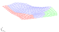
The properties of all 2D mesh data that GMS displays on the screen can be controlled through the 2D Mesh tab of the Display Options dialog. This dialog is opened by right-clicking on the File:2DMeshFolder.GIF 2D Mesh Data entry in the Project Explorer and selecting the Display Options command. It can also be accessed from the from the Display menu or the File:Dispopts.gif Display Options macro. The following table describes the display options available for the 2D Mesh module.
| Display Option | Description |
|---|---|
| Nodes | The Nodes item is used to display mesh nodes. A small circle is drawn at each node. |
| Element edges | The Elements item is used to display the edges of elements. The elements can be drawn using either the default color for elements or using the color of the material associated with each element.
The color of the element edges can be adjusted according to the following options:
|
| Element faces | This option fills the elements with the material color. |
| Texture map image | The Texture Map Image Item is used to "drape" an image over the surface of the 2D Mesh. |
| Mesh boundary | The Mesh boundary item is used to display a solid line around the perimeter of the mesh. Displaying the boundary is useful when contours are being displayed with the element edges turned off. |
| Node numbers | The Node Numbers item is used to display the ID associated with each node next to the node. |
| Element numbers | The Element numbers item is used to display the ID associated with each element at the centroid of the element. |
| Thin elements | If the Thin elements item is set, triangular elements with small aspect ratios are highlighted. The minimum aspect ratio can be set using the Aspect Ratio command in the Modify Mesh menu. |
| Scalar values | The Scalar Values item is used to display the scalar values of the active dataset for each node next to the node. |
| Contours | Most of the objects supported by GMS can be contoured by turning on the Contour Options in the Display Options dialog. When an object is contoured, the values associated with the active dataset for the object are used to generate the contours. |
File:Display2Dmesh.jpg
The Display Options dialog showing the 2D Mesh tab.
| [hide]GMS – Groundwater Modeling System | ||
|---|---|---|
| Modules: | 2D Grid • 2D Mesh • 2D Scatter Point • 3D Grid • 3D Mesh • 3D Scatter Point • Boreholes • GIS • Map • Solid • TINs • UGrids | |
| Models: | FEFLOW • FEMWATER • HydroGeoSphere • MODAEM • MODFLOW • MODPATH • mod-PATH3DU • MT3DMS • MT3D-USGS • PEST • PHT3D • RT3D • SEAM3D • SEAWAT • SEEP2D • T-PROGS • ZONEBUDGET | |
| Aquaveo | ||
Hidden category:
