GMS:2D Mesh Tool Palette
The following tools are contained in the dynamic portion of the Tool Palette when the 2D Mesh Module is active. Only one tool is active at any given time. The action that takes place when the user clicks in the Graphics Window depends on the current tool. The following table describes the tools in the 2D Mesh tool palette.
| Tool | Tool Name | Description |
|---|---|---|
| Select Nodes | The Select Nodes tool is used to select a set of nodes for some subsequent operation such as deletion. The coordinates of a selected node can be edited by dragging the node while this tool is active. The coordinates of selected nodes can also be edited using the Edit Window. A node can also be selected by using the Find Node command in the Mesh menu. The user is prompted for a node ID and the node is selected. Any previously selected nodes are unselected. | |
| File:Tool SelectTriangles.png | Select Elements | The Select Elements tool is used to select a set of elements for operations such as deletion or assigning a material type. An element can also be selected by using the Find Element command in the Mesh menu. The user is prompted for an element ID and the element is selected. Any previously selected elements are unselected. |
| File:Tool SelectVertexString.png | Select Node Strings | The Select Node Strings tool is used to select one or more strings of nodes. Node strings are used for operations such as adding breaklines to the mesh.
The procedure for selecting node strings is somewhat different than the normal selection procedure. Strings are selected as follows:
To remove the last node from a string, press the Backspace key. To abort entering a node string, press the ESC key. To end a node string, press Return or double-click on the last node in the string. Another node string can then be selected. |
| Create Nodes | The Create Nodes tool is used to manually add nodes to a mesh. When this tool is selected, clicking on a point within the Graphics Window will place a node at that point. What happens to the node after it is added (whether and how it is triangulated into the mesh) depends on the settings in the Node Options dialog in the Modify Mesh menu. | |
| File:Tool CreateLinTriElement.png | Create Linear Triangle Element | Four types of elements are supported by the 2D Mesh module:
Elements can be created using automatic meshing techniques such as triangulation. However, it is often necessary to edit a mesh by creating elements one at a time using the four Create Element tools. See the "Creating an Element" section below. |
| File:Tool CreateQuadLinElement.png | Create Quadratic Triangle Element | |
| File:Tool CreateLinQuadElement.png | Create Linear Quadrilateral Element | |
| File:Tool CreateQuadQuadElement.png | Create Quadratic Quadrilateral Element | |
| File:Tool MergeSplit.png | Merge/Split | If the Merge/Split tool is selected, clicking on a triangle edge with the mouse cursor will cause the two triangular elements adjacent to the edge to be merged into a quadrilateral element provided that the quadrilateral shape formed by the two triangles is not concave.
The Merge/Split tool can also be used to undo a merge or to "unmerge" a quadrilateral element. A quadrilateral element can be split into two triangles by clicking anywhere in the interior of the element. This tool is useful if a pair of triangles are inadvertently merged. |
| File:Tool SwapEdges.png | Swap Edges | If the Swap Edges tool is selected, clicking on the common edge of two adjacent triangles will cause the edge to be swapped as long as the quadrilateral shape formed by the two triangles is not concave.
Occasionally, it is useful to interactively or manually swap the edges of two adjacent triangles. This can be thought of as a quick and simple alternative to adding breaklines to ensure that the edges of the triangular elements honor a geometrical feature that needs to be preserved in the mesh. |
| Contour Labels | The Contour Label tool is used to manually place numerical contour elevation labels at points clicked on with the mouse. These labels remain on the screen until the contour options are changed, until they are deleted using the Contour Labels dialog, or until the mesh is edited in any way. Contour labels can be deleted with this tool by holding down the Shift key while clicking on the labels. This tool may only be used when the 2D mesh is in plan view. |
Creating an Element
A single element can be constructed from a set of existing nodes using the following steps:
- Select the tool corresponding to the type of element to be created.
- Select the nodes corresponding to the corner nodes of the element in consecutive order around the perimeter of the element. The nodes can be selected in either clockwise or counter-clockwise order. It is also possible to build an element by dragging a rectangle to enclose the nodes making up the new element rather than selecting each node one by one. A beep will sound if the wrong number of nodes for the current element type are selected.
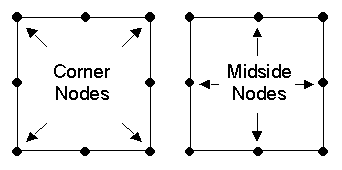
If the current element type is a quadratic element (six or eight node element), the midside nodes of the element are created automatically. If the new element is adjacent to an existing element, the midside node of the existing element is used for the new element and a new midside node is not created, i.e. midside nodes are not duplicated.The coordinates of midside nodes cannot be edited. Midside nodes are always assumed to be located at the midpoint of the two adjacent corner nodes. When a corner node is edited, the coordinates of the adjacent midside nodes are updated accordingly.
GMS performs several checks when a new element is constructed. The new element is checked to see whether or not it is ill-formed (the element has a twist in it or is self intersecting). The element is also checked to see if it overlaps any of the elements adjacent to the nodes comprising the new element. In addition, the elements adjacent to a new element are checked to ensure that the elements are conforming, i.e. linear elements (three and four node elements) are not allowed to be placed adjacent to quadratic elements (six and eight node elements). If any of the above checks fail, the construction of the new element is aborted
| GMS – Groundwater Modeling System | ||
|---|---|---|
| Modules: | 2D Grid • 2D Mesh • 2D Scatter Point • 3D Grid • 3D Mesh • 3D Scatter Point • Boreholes • GIS • Map • Solid • TINs • UGrids | |
| Models: | FEFLOW • FEMWATER • HydroGeoSphere • MODAEM • MODFLOW • MODPATH • mod-PATH3DU • MT3DMS • MT3D-USGS • PEST • PHT3D • RT3D • SEAM3D • SEAWAT • SEEP2D • T-PROGS • ZONEBUDGET | |
| Aquaveo | ||

