GMS:MF6 DIS Package
From XMS Wiki
Jump to navigationJump to search
| This contains information about functionality available starting at GMS version 10.5. The content may not apply to other versions. |
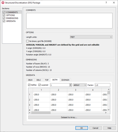
The Structured Discretization (DIS) Package dialog is accessed by double-clicking on the DIS package under a MODFLOW 6 simulation in the Project Explorer. The DIS package contains discretization information for the simulation. It contains the following sections and options:
- Sections list – A list of sections that can be turned on or off:
- Comments – Turn on to make the Comments section visible.
- Options – Turn on to make the Options section visible.
- Dimensions – Turn on to make the Dimensions section visible.
- GridData – Turn on to make the GridData section visible. This section is on by default.
- Comments section – Enter general alphanumeric comments. Comments entered here get written at the top of the file, preceded by a '#' symbol.
- Options section
- Length units – A drop-down with options specifying the length units used for this model:
- "Feet"
- "Meters"
- "Centimeters"
- "Unknown"
- No binary grid file (NOGRB) – Turn on to deactivate writing of the binary grid file.
- X origin (XORIGIN) – Defined by the grid and not user editable here.
- Y origin (YORIGIN) – Defined by the grid and not user editable here.
- Rotation angle (ANGROT) – Defined by the grid and not user editable here.
- Length units – A drop-down with options specifying the length units used for this model:
- Dimensions section – This is an informational section displaying the number of layers (NLAY), number of rows (NROW), and number of columns (NCOL). These are defined by the grid and not user editable here.
- GridData section – Contains a number of tabs, including:
- DELR – Column spacing in the row direction. Defined by the grid and not user editable here.
- DELC – Row spacing in the column direction. Defined by the grid and not user editable here.
- TOP – Top elevation for each cell in the top model layer.
- Layered – This option is not available as there is only one top layer.
- If "Constant" is selected from the drop-down, enter a decimal value in the Constant field to be applied to all cells in the top model layer.
- If "Array" is selected from the drop-down, a user-editable array appears below the drop-down. Enter a decimal Factor value to the right of the drop-down. The individual elements of the array are multiplied by the factor value after they are read.
- BOTM – Bottom elevation for each cell.
- Layered – Turn on if there is more than one bottom layer. Select the desired layer from the drop down in order to edit the array (if "Array" is selected from the drop-down).
- If "Constant" is selected from the drop-down, enter a decimal value in the Constant field to be applied to all cells in the bottom model layer(s).
- If "Array" is selected from the drop-down, a user-editable array appears below the drop-down. Enter a decimal Factor value to the right of the drop-down. The individual elements of the array are multiplied by the factor value after they are read.
- Dataset to Array... – Click to open the Select Dataset dialog. Select the desired database(s) in this dialog.
- IDOMAIN – Optional. Characterizes the existence status of a cell. Setting a value of "0" for a particular cell inactivates that cell so it is not used in the simulation.
- Define – Turn on to define an IDOMAIN.
- Layered – Turn on if there is more than one bottom layer. Select the desired layer from the drop down in order to edit the array (if "Array" is selected from the drop-down).
- If "Constant" is selected from the drop-down, enter a decimal value in the Constant field to be applied to all cells in the IDOMAIN layer(s).
- If "Array" is selected from the drop-down, a user-editable array appears below the drop-down. Enter a decimal Factor value to the right of the drop-down. The individual elements of the array are multiplied by the factor value after they are read.
- Dataset to Array... – Click to open the Select Dataset dialog. Select the desired database(s) in this dialog.
Related Topics
GMS – Groundwater Modeling System | ||
|---|---|---|
| Modules: | 2D Grid • 2D Mesh • 2D Scatter Point • 3D Grid • 3D Mesh • 3D Scatter Point • Boreholes • GIS • Map • Solid • TINs • UGrids | |
| Models: | FEFLOW • FEMWATER • HydroGeoSphere • MODAEM • MODFLOW • MODPATH • mod-PATH3DU • MT3DMS • MT3D-USGS • PEST • PHT3D • RT3D • SEAM3D • SEAWAT • SEEP2D • T-PROGS • ZONEBUDGET | |
| Aquaveo | ||
