GMS:Contour Options
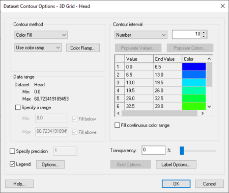
The options used to generate contours can be edited by selecting the Contour Options command in the Display menu. The items in the Contour Options dialog are as follows:
General vs. Grid Layers
There are two tabs associated with the Contour Options dialog. The options described below are for the General options. The Grid Layers options are used when contouring 3D grids.
Contour Method
There are 3 main types of contours: linear, color filled, and both linear and color filled.
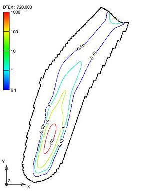
- Linear – The default method is Normal linear contours and causes the contours to be displayed as piece-wise linear strings.
- Color Fill – If the Color fill between contours option is selected, the region between adjacent contour lines is filled with a solid color. There is also a smooth option available. When this option is turned on the color between contour lines varies according to the color ramp. The transparency of the filled contours can also be adjusted.
- Linear and Color Fill – This option shows linear contours on top of color filled contours.
- Block Fill - This option applies only to cell centered grids. Cells are filled with a single color. The color chosen corresponds to the color ramp value associated with the value at the cell center.
Line options
- Bold contours – The Bold every... option can be used to display contours at selected intervals with a thicker line width.
- Contour labels – The Label every... option can be used to plot labels on contours at selected intervals. The contour label options are edited using the Contour Labels dialog.
Data Range
The values shown in the Data range section correspond to the maximum and minimum values in the active dataset. These values are sometimes useful when choosing an appropriate contour interval.
- Use each timestep's max and min – This option is only applicable if contours are colored according to a color ramp, and the dataset has more than one time step. If this option is on, the maximum and minimum color ramp colors will be displayed for every timestep. Otherwise, the maximum and minimum colors apply to the entire dataset and therefore will only appear when the current dataset contains the dataset maximum or minimum value.
- Contour Specified Range – Regardless of which option is selected for the contour interval, a maximum and a minimum contour value can be specified and the contouring can be restricted to the specified range. If desired, the fill below or fill above options can be turned on to color fill above/below the specified range.
Contour Interval
The contour interval defines the values associated with the contours. Based on the option selected, the contour values are computed and displayed in the spreadsheet. The colors of the contours will also be displayed if a Color Ramp is being used.
Three options are provided for defining contour intervals in the Contour Options dialog. The options are as follows:
Number of Contours – With the Number of Contours option, an integer is entered representing the total number of contours. The contour interval is adjusted based on the current active dataset so that the contours are evenly spaced and the number of contours correspond exactly to the specified value.
Specified Interval – Directly specifies the contour interval (5, 10, 20, etc.).
Specified Values – Allows entering a list specific contour values. Contours are only generated at these values.
Contour Labels
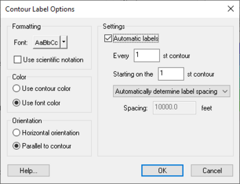
The Label Options button in the Contour Options dialog is used to access the Contour Label Options dialog. This dialog is used to set the label color, the number of decimal places used to plot the label, and the spacing used when the labels are generated automatically. The default spacing value controls the placement of labels when labels are generated automatically.
Labels can be added to contours in one of two ways:
- If the contour label option is selected in the Contour Options dialog, labels are automatically placed on the contours. The spacing of the labels is controlled with the Contour Labels dialog.
- In some modules, contour labels can be added manually to contours by selecting the Contour Labels tool in the Tool Palette and clicking on the contours where labels are desired. By default, the dataset value corresponding to the point that was clicked is computed and a label corresponding to the nearest contour value is drawn centered at the point that was clicked. An option can be set in the Contour Label Options dialog to use the exact value at the point that is clicked as opposed to using the nearest contour value. This option is useful to post dataset value labels in regions where there are no contours.
Specified Dataset
Specify the dataset with the Select Dataset... button in the 3D Grid Data tab of the Display Options dialog. This brings up a new window where the specified dataset is selected. The contour options available for the specified dataset are the same as the active dataset options, yet each must be establish separately. This option is useful in comparing datasets.
Grid Layer Contour Options
When contouring 3D grid data, there are additional options available in the Contour Options dialog. These options lets chosing the data to contour. The default array used to fill cells is the active dataset. Another option for filling cells is the data colors option; this uses an input array from MODFLOW, MODPATH, MT3DMS, SEAM3D, or RT3D. Any of the input arrays from the models such as Kh, Kv, Recharge, etc. can be displayed, for any stress period. For MT3DMS/RT3D/SEAM3D, also specify the species.
Interpolation
GMS interpolates data from the cell centers (for cell-centered grids) to the cell corners and midsides so that the grid can be triangulated and contoured. By default, GMS uses a fast algorithm for interpolating the data that is adequate for the majority of situations. If the Auto-interpolate contours option is turned off, specify a customized interpolation scheme. By default, GMS truncates the interpolated values to the max and min of the data, but the option can be turned off.
Contour Legend Options
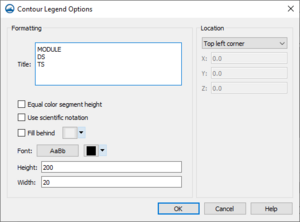
The Contour Legend Options controls the formatting and location of a displayed legend. If a contour dataset exists and is displayed, the legend will be shown if the Legend check box on the Contour Display Options dialog is checked. This window is accessed only from the Legend Options button on the Contour Display Options page of the Display Options dialog.
The Formatting section includes fields for the Title and Units displayed with the legend, a Font selection button for text style, and Height and Width fields for legend size.
Since contour datasets can be displayed for multiple modules at the same time and, therefore, multiple contour legends can be displayed, the Title field can include keywords for convenient labeling. The following title keywords are case sensitive:
- "MODULE" – will be replaced with the title of the contour dataset's module
- "DS" – will be replaced with the name of the currently selected contour dataset
- "DS:TS" – will be replaced with the name of the currently selected contour dataset followed by the current time step
A title of "MODULE DS:TS" is best since it will automatically update as contour dataset selection changes.
The Units field includes the single case sensitive keyword of "DEFAULT", which will be replaced with the velocity units of meters per second (m/s) or feet per sceond (ft/s) based on the current coordinate system's horizontal units.
The Location section includes a combo box for specifying the location of the displayed legend. The locations include:
- Top left corner
- Bottom left corner
- Top right corner
- Bottom right corner
- Screen location – specify the location based on screen precentages
- World location – specify the coordinate location
GMS – Groundwater Modeling System | ||
|---|---|---|
| Modules: | 2D Grid • 2D Mesh • 2D Scatter Point • 3D Grid • 3D Mesh • 3D Scatter Point • Boreholes • GIS • Map • Solid • TINs • UGrids | |
| Models: | FEFLOW • FEMWATER • HydroGeoSphere • MODAEM • MODFLOW • MODPATH • mod-PATH3DU • MT3DMS • MT3D-USGS • PEST • PHT3D • RT3D • SEAM3D • SEAWAT • SEEP2D • T-PROGS • ZONEBUDGET | |
| Aquaveo | ||


