SMS:Film Loop Flow Trace Options: Difference between revisions
From XMS Wiki
Jump to navigationJump to search
No edit summary |
No edit summary |
||
| (17 intermediate revisions by the same user not shown) | |||
| Line 1: | Line 1: | ||
This page of the Film Loop Setup wizard allows | [[File:FilmLoopFlowTrace.png|thumb|375 px|''Film Loop Setup – Flow Trace Options'' dialog in the ''Film Loop Wizard''.]] | ||
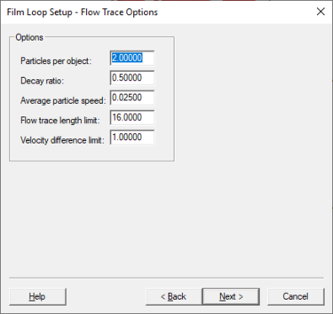
This page of the ''Film Loop Setup'' wizard allows setting up options for the particles in the flow trace. The following options are available: | |||
* | * ''Particles per object'' – Increasing this value increases the total number of random particles that get created and distributed throughout the domain. For a finite element mesh, the number specified is multiplied by the number of elements to determine the number of particles to be distributed over the domain. | ||
* | * ''Decay Ratio'' – This defines how quickly the particle’s tail decays and should be a value between zero (0.0) and one (1.0). A larger value produces particles with longer tails. A value of 1.0 indicates that it will take 100 percent of the film loop time for a end of a tail to fade away. | ||
* | * ''Average particle speed'' – This provides a means of magnifying or reducing the activity in the domain. The particles will be traced through the domain with the velocity of the current vector functional dataset. The velocity is assumed as pixel space units. No time match between distance on the screen and velocity is attempted because the time between flow trace frames is not explicit. If an exact velocity in distance is desired, compute the scale value and specify it here. Normally, for visualization purposes, experimentation with this parameter will generate the desired results. Another option would be to use the drogue animation tools. | ||
* | * ''Flow trace length limit'' – This specifies a maximum distance the particle can travel in a single numerical integration step. When computing the numerical integration, if a particle travels more than this distance, the integration step is reduced to produce a more accurate particle path. Decreasing this number causes slower integration, but a more accurate path. | ||
* | * ''Velocity difference limit'' – This specifies a maximum change in speed the particle can experience in a single numerical integration step. When computing the numerical integration, if a particle speed changes more than this limit, the integration step is reduced to produce a more accurate particle path. Decreasing this number causes slower integration, but a more accurate path. | ||
SMS will use the current background as the background for the drogue plots. The model domain is always black and particles are always white. These two options cannot be changed. | |||
| Line 17: | Line 18: | ||
* [[SMS:Animations|Animations]] | * [[SMS:Animations|Animations]] | ||
{{Template: | |||
{{Template:Navbox SMS}} | |||
[[Category:Animation|F]] | |||
[[Category:Animation Dialogs|F]] | |||
Latest revision as of 20:57, 26 September 2019
This page of the Film Loop Setup wizard allows setting up options for the particles in the flow trace. The following options are available:
- Particles per object – Increasing this value increases the total number of random particles that get created and distributed throughout the domain. For a finite element mesh, the number specified is multiplied by the number of elements to determine the number of particles to be distributed over the domain.
- Decay Ratio – This defines how quickly the particle’s tail decays and should be a value between zero (0.0) and one (1.0). A larger value produces particles with longer tails. A value of 1.0 indicates that it will take 100 percent of the film loop time for a end of a tail to fade away.
- Average particle speed – This provides a means of magnifying or reducing the activity in the domain. The particles will be traced through the domain with the velocity of the current vector functional dataset. The velocity is assumed as pixel space units. No time match between distance on the screen and velocity is attempted because the time between flow trace frames is not explicit. If an exact velocity in distance is desired, compute the scale value and specify it here. Normally, for visualization purposes, experimentation with this parameter will generate the desired results. Another option would be to use the drogue animation tools.
- Flow trace length limit – This specifies a maximum distance the particle can travel in a single numerical integration step. When computing the numerical integration, if a particle travels more than this distance, the integration step is reduced to produce a more accurate particle path. Decreasing this number causes slower integration, but a more accurate path.
- Velocity difference limit – This specifies a maximum change in speed the particle can experience in a single numerical integration step. When computing the numerical integration, if a particle speed changes more than this limit, the integration step is reduced to produce a more accurate particle path. Decreasing this number causes slower integration, but a more accurate path.
SMS will use the current background as the background for the drogue plots. The model domain is always black and particles are always white. These two options cannot be changed.
Related Topics
SMS – Surface-water Modeling System | ||
|---|---|---|
| Modules: | 1D Grid • Cartesian Grid • Curvilinear Grid • GIS • Map • Mesh • Particle • Quadtree • Raster • Scatter • UGrid |  |
| General Models: | 3D Structure • FVCOM • Generic • PTM | |
| Coastal Models: | ADCIRC • BOUSS-2D • CGWAVE • CMS-Flow • CMS-Wave • GenCade • STWAVE • WAM | |
| Riverine/Estuarine Models: | AdH • HEC-RAS • HYDRO AS-2D • RMA2 • RMA4 • SRH-2D • TUFLOW • TUFLOW FV | |
| Aquaveo • SMS Tutorials • SMS Workflows | ||
