SMS:SRH-2D Coverages: Difference between revisions
| Line 25: | Line 25: | ||
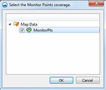
[[File:SRHmonitorpointscoverage.jpg|thumb|220 px|The SRH ''Select the Monitor Points coverage'' dialog.]] | [[File:SRHmonitorpointscoverage.jpg|thumb|220 px|The SRH ''Select the Monitor Points coverage'' dialog.]] | ||
Monitor Points are optional. If choosing to have monitor points, the user should create a monitor points coverage and add points using the '''Create Feature Point''' tool. A monitor point is used to gather specific information for that location at all time steps. Information calculated by SRH at a monitor point includes position in the X and Y direction, bed elevation, water elevation, water depth, X direction velocity component, Y direction velocity component, velocity magnitude, Froude number, and shear stress. If a Monitor Points | Monitor Points are optional. If choosing to have monitor points, the user should create a monitor points coverage and add points using the '''Create Feature Point''' tool. A monitor point is used to gather specific information for that location at all time steps. Information calculated by SRH at a monitor point includes position in the X and Y direction, bed elevation, water elevation, water depth, X direction velocity component, Y direction velocity component, velocity magnitude, Froude number, and shear stress. | ||
If a Monitor Points coverage has been created, then it must be linked to the SRH-2D simulation. This can be done by dragging the coverage under the simulation item in the Project Explorer or right-clicking on the coverage and using the ''Link to'' menu item. | |||
IN SMS 11.2 only, the Monitor Points coverage must be assigned and selected in the ''Select the Monitor Point Coverage'' dialog for SRH to recognize them. The dialog is accessed through the '''Assign Monitor Points Coverage''' command in the ''SRH-2D'' menu. | |||
==Materials Coverage== | ==Materials Coverage== | ||
Revision as of 18:23, 24 June 2015
Boundary Conditions Coverage
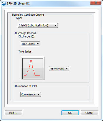
SRH support a variety of boundary conditions for hydraulic computation. The boundary conditions for the model are specified through the SRH Boundary Condistion coverage by selecting an arc or by selecting a nodestring in the mesh. Once the arc or nodestring has been selected, double-clicking, or right-clicking and using the Assign Linear BC... command, will bring up a dialog where the boundaries can be assigned.
All currently supported boundary types are exterior boundaries with the exception of a monitor line. Other boundary types include the following: Inlet-Q, Inlet-SC, Exit-EX, Exit-H, Exit-Q, Wall, and Symmetry.
- Inlet-Q is a subcritical inlet boundary that may be given as a constant discharge or as a variable discharge hydrograph. The velocity distribution type may be selected from the boundary condition menu.
- Inlet-SC is a supercritical inlet boundary that may be given as a constant discharge or as a variable discharge hydrograph. Inlet-SC also requires information about depth. Within the boundary condition menu, the velocity distribution type may be specified.
- Exit-EX is a supercritical exit boundary condition.
- Exit-H is a stage type exit boundary where water surface elevation may be given as a constant number or as a stage-discharge or rating curve.
- Exit-Q is and exit boundary with a discharge given as a constant number or as a hydrograph.
Obstructions Coverage
Used to create feature objects that represent obstructions, such as bank protrusions and boulder clusters. Obstructions can be assigned to feature arcs. When this coverage is active, double-clicking on a feature arc, or right-clicking on an arc and selecting the Assign Obstructions... command, will bring up the Obstructions dialog.
The Obstructions dialog has the following options:
- Obstruction Width/Diameter
- Obstruction Thickness (Z-dir)
- Drag Coefficient (Cd)
- Units – may be assigned to either "ft" (feet) or "m" (meters).
- Porisity
Monitor Points Coverage
Monitor Points are optional. If choosing to have monitor points, the user should create a monitor points coverage and add points using the Create Feature Point tool. A monitor point is used to gather specific information for that location at all time steps. Information calculated by SRH at a monitor point includes position in the X and Y direction, bed elevation, water elevation, water depth, X direction velocity component, Y direction velocity component, velocity magnitude, Froude number, and shear stress.
If a Monitor Points coverage has been created, then it must be linked to the SRH-2D simulation. This can be done by dragging the coverage under the simulation item in the Project Explorer or right-clicking on the coverage and using the Link to menu item.
IN SMS 11.2 only, the Monitor Points coverage must be assigned and selected in the Select the Monitor Point Coverage dialog for SRH to recognize them. The dialog is accessed through the Assign Monitor Points Coverage command in the SRH-2D menu.
Materials Coverage
The SRH-2D Materials Coverage allows creating material zones specific to the SRH-2D model. Material zones are assigned using polygons in the coverage.
See SRH Material Properties for more information.
Related Topics
SMS – Surface-water Modeling System | ||
|---|---|---|
| Modules: | 1D Grid • Cartesian Grid • Curvilinear Grid • GIS • Map • Mesh • Particle • Quadtree • Raster • Scatter • UGrid |  |
| General Models: | 3D Structure • FVCOM • Generic • PTM | |
| Coastal Models: | ADCIRC • BOUSS-2D • CGWAVE • CMS-Flow • CMS-Wave • GenCade • STWAVE • WAM | |
| Riverine/Estuarine Models: | AdH • HEC-RAS • HYDRO AS-2D • RMA2 • RMA4 • SRH-2D • TUFLOW • TUFLOW FV | |
| Aquaveo • SMS Tutorials • SMS Workflows | ||

