SMS:UGrid Display Options
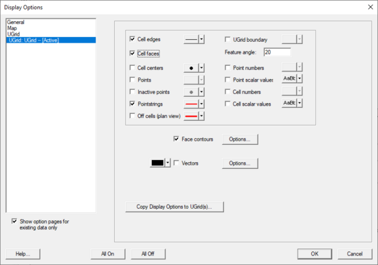
The display options of UGrid data that SMS displays on the screen can be controlled through the UGrid Data tab of the Display Options dialog. This dialog is opened by right-clicking on the ![]() "UGrid Data" item in the Project Explorer and selecting the Display Options command. It can also be accessed from the from the Display menu or the Display Options
"UGrid Data" item in the Project Explorer and selecting the Display Options command. It can also be accessed from the from the Display menu or the Display Options ![]() macro. The following table describes the display options available for the UGrid module.
macro. The following table describes the display options available for the UGrid module.
When multiple UGrids exist in a project, each UGrid will be shown in the Display Options dialog. The display options for each UGrid in the project can be set separately.
| Display Option | Description |
|---|---|
| Cell edges | The Cell edges item is used to display the edges of cells. The cells are drawn using the specified color. |
| Cell faces | This option fills the cells with the material color. |
| Cell centers | This option displays a point at the center of every cell. |
| Points | Points are the corners of cells, or simply 3D points not attached to cells. A symbol can be displayed at these locations. If Point contours are on, the color of the symbol will be determined by the data and the contour options. |
| Inactive points | Show points that correspond with an inactive dataset value. |
| UGrid Boundary | Used to display an edge for each of the edges on the exterior of the set of all cells (visible or invisible) which corresponds to a discontinuity in the UGrid exterior. This display option provides a helpful spatial context when displaying isosurfaces or cross sections. |
| Feature angle | The UGrid boundary feature angle is used only when the UGrid Boundary option is selected. This angle represents a threshold angle at which an edge of the shell will be displayed. If for example, an angle of 45 degrees is defined, any edge of the UGrid which divides two cell faces that are at an angle greater than 45 degrees to each other will not be displayed. |
| Point numbers | The Point numbers item is used to display the ID associated with each point next to the point. |
| Cell numbers | The cell numbers item is used to display the ID associated with each cell at the centroid of the cell. |
| Scalar values | The Scalar Values item is used to display the scalar values of the active dataset for each node next to the node. |
| Face contours | Most of the objects supported by SMS can be contoured by turning on the Contour Options in the Display Options dialog. When an object is contoured, the values associated with the active dataset for the object are used to generate the contours. |
| Point contours | The same Contour Options but applied to points. |
| Vectors | Vector arrows are displayed using the active vector dataset. |
| Isosurfaces | Isosurfaces are the 3D equivalent of a contour line. An isosurface is a surface of constant value extracted from a 3D dataset. |
| Clip | Creates a clipping widget that can be used to hide part of the UGrid. Clicking the Options button will bring up the UGrid Clip Settings dialog. The options include setting the widget to be a plane, which can be manipulated with the mouse in the Graphics Window, or to be a scalar or scalar range, which work like isosurfaces. Whole cells or partial cells can be clipped. |
| Copy Display Options to UGrid(s) | The current UGrid Display Options can be copied to other UGrids. This button brings up a dialog to select the UGrids that the Display Options will be copied to. |
Functional Surfaces
A functional surface is exactly that. It is a surface representing one of the functional datasets associated with an unstructured grid. The most intuitive example of a functional surface is the display of the water surface over a model's bathymetry. In this case, the surface represents an actual physical surface, but the functional surface could just as easily represent the velocity magnitude, or concentration, or any other scalar quantity.
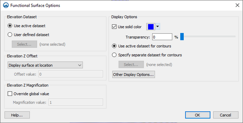
To create/display functional surfaces, right-click on the UGrid in the Project Explorer and select New Functional Surface. Then specify the surface attributes which include:
- Elevation Dataset – Selects which dataset is to be used to form the functional surface.
- Use active dataset – The currently selected dataset will be used for the functional surface.
- User defined dataset – Allows selecting a specific dataset in the project to use for the functional surface. The Select button for this option will bring a Select Dataset dialog.
- Elevation Z Offset – SMS displays functional surfaces at a simulated z-value. This may be the actual surface value (such as is the case with water surfaces elevations), but more often the value will not have a physical meaning, and may intersect the bathymetry or not even be in the same area. For this reason, SMS offers options for placing the functional surface at one of the following locations:
- "Display surface at location" – The functional surface will be displayed at the location of the dataset on the geometry.
- "Display surface above geometry" – The functional surface will be displayed slightly above the geometry based on the z-magnification.
- "Display surface with user defined offset" &dnash; The functional surface will be display based on a value entered by the user.
- Offset value – Enter an offset Z value for the user defined offset.
- Elevation Z Magnification – Functional data may not vary significantly when compared to the horizontal extents of the model. For this reason, the interface allows magnification (scaling) of the functional surface. By default, the surface is scaled based on the global z-magnification specified in the general display options. This may be overridden.
- Override global value – Turn on to override the global Z magnification value.
- Magnification value – Enter a z magnification value to override the global value.
- Override global value – Turn on to override the global Z magnification value.
- Display Options – Controls the color of the functional surface. It may be a constant color or colored based on the contour colors specified. The colors may be associated with the value of the functional surface, or another dataset. The surface may also be partially transparent.
- Use solid color – Will change the functional surface to be a single color.
- Color – Select a color to use as the solid color for the functional surface.
- Transparency – Set a transparency level for the functional surface. The transparency by entering a value or using the slider.
- Contour surface – Sets specific contour options for the functional surface.
- Options – Will open the Dataset Contour Options dialog.
- Specify separate dataset for contours – Allows a different dataset to be used for the contour options.
- Select – Brings up a Select Dataset dialog.
- Other Display Options – Brings up the Functional Surface Other Options dialog.
- Use solid color – Will change the functional surface to be a single color.
Functional Surface Other Options
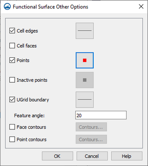
Additional display options can be set for functional surfaces with UGrids. These options are reached through the Functional Surface Options dialog. The Functional Surface Other Options dialog includes the following:
- Cell edges – Turn on to display cell edge lines on the functional surface. Clicking the button next to this option will open the Line Properties dialog.
- Cell faces – Turn on to display cell faces on the functional surface.
- Points – Turn on to display points along the functional surface. Clicking the button next to this option will open the Symbol Attributes dialog.
- Inactive points – Turn on to display inactive points along the functional surface. Clicking the button next to this option will open the Symbol Attributes dialog.
- UGrid boundary – Turn on to display grid boundary line on the functional surface. Clicking the button next to this option will open the Line Properties dialog.
- Feature angle – Enter the feature angle value for the functional surface.
- Face contours – Turn on to see contours on the faces of the functional surface. Clicking the button next to this option will open the Contour Options dialog.
- Point contours – Turn on to see contours on the points of the functional surface. Clicking the button next to this option will open the Contour Options dialog.
Related Topics
SMS – Surface-water Modeling System | ||
|---|---|---|
| Modules: | 1D Grid • Cartesian Grid • Curvilinear Grid • GIS • Map • Mesh • Particle • Quadtree • Raster • Scatter • UGrid |  |
| General Models: | 3D Structure • FVCOM • Generic • PTM | |
| Coastal Models: | ADCIRC • BOUSS-2D • CGWAVE • CMS-Flow • CMS-Wave • GenCade • STWAVE • WAM | |
| Riverine/Estuarine Models: | AdH • HEC-RAS • HYDRO AS-2D • RMA2 • RMA4 • SRH-2D • TUFLOW • TUFLOW FV | |
| Aquaveo • SMS Tutorials • SMS Workflows | ||


