GMS:Converting a 2D Mesh to Other Types of Data
2D meshes may be converted to other types of data used in GMS, such as a TIN or 2D scatter points. 2D meshes are converted by using the following commands in the Mesh menu:
Mesh → 2D Scatter Points
The Mesh → 2D Scatter Points command in the Mesh menu is used to create a new scatter point set using the nodes in a mesh. A copy is made of each of the datasets associated with the mesh and the datasets are associated with the new scatter point set.
Mesh → TIN
A new TIN can be created from a 2D finite element mesh by selecting the Mesh → TIN command from the Build Mesh menu. A triangle is created from each triangular element in the mesh and two triangles are created from each quadrilateral element in the mesh by splitting the quadrilateral element along the shortest diagonal.
Mesh → 3D Tets
The Mesh→3D Tets command in the Mesh menu is used to convert a 2D mesh to a 3D mesh of tetrahedron.
This command brings up the Mesh→3D Tets dialog. At the top of the dialog, select two datasets that will represent the Top elevation and the Bottom elevation of the 3D mesh. In general the top elevation dataset should be completely above the bottom elevation dataset. Also select how the 3D mesh will be extruded. There are two options: Constant number of layers and Layers distributed by depth. When using Constant number of layers, simply enter the number of layers in the edit field. When using the Layers distributed by depth, enter a maximum layer thickness for each material present in the 2D mesh in the spread sheet.
How it works
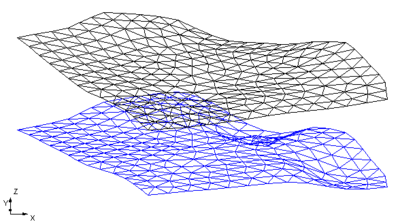
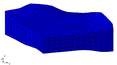
Specify a top and bottom elevation dataset and the 3D mesh is extruded between the two datasets. This process is illustrated in the figures below.
Two methods are available for determining the number of 3D mesh nodes to place between the two surfaces: Constant number of layers and Layers distributed by depth.
- The first option is a constant number of layers. The figure above was created by specifying 4 layers between the top and bottom surface. In this case five 3D mesh nodes are created between the top and bottom elevation datasets creating 4 layers.
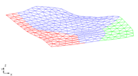
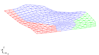
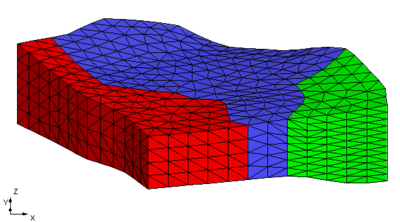
- The second option uses the materials assigned to the 2D mesh. Then specify a maximum layer thickness for each of the materials. Then as the 3D mesh is extruded the number of nodes will vary depending on the material and the distance between the top and bottom elevation. This is illustrated in the figures below. The first figure show a 2D mesh with 3 materials assigned to it.
A maximum layer thickness was assigned to each of the materials: red = 14.0 ft., blue = 10.0 ft., and green = 6.0 ft. The resulting 3D mesh is shown below.
| GMS – Groundwater Modeling System | ||
|---|---|---|
| Modules: | 2D Grid • 2D Mesh • 2D Scatter Point • 3D Grid • 3D Mesh • 3D Scatter Point • Boreholes • GIS • Map • Solid • TINs • UGrids | |
| Models: | FEFLOW • FEMWATER • HydroGeoSphere • MODAEM • MODFLOW • MODPATH • mod-PATH3DU • MT3DMS • MT3D-USGS • PEST • PHT3D • RT3D • SEAM3D • SEAWAT • SEEP2D • T-PROGS • ZONEBUDGET | |
| Aquaveo | ||
