SMS:GenCade Model Control Dialog
From XMS Wiki
(Redirected from SMS:GenCade Model Control)
Jump to navigationJump to search
The Gencade Model Control dialog is used to set beach conditions, lateral boundary conditions and general simulation options. This document highlights the more commonly used options. Refer to the GenCade web site for a more detailed description of how these parameters affect the model results.
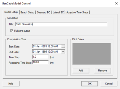
Model Setup Tab
The following parameters are specified in the model setup tab:
- Simulation
- Title – Title of simulation run.
- Full print output – Path and name of printed output file.
- Computational Time
- Start Date – Simulation start date.
- End Date – Simulation end date.
- Time Step – Model time step in hours.
- Recording Time Step – Recorded model time step in hours.
- Print Dates – Dates to save simulated shoreline. Use the Add button to create dates and the Remove button to delete any unwanted dates.
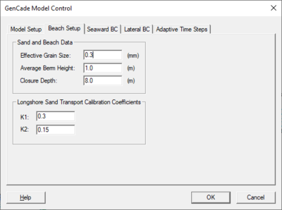
Beach Setup Tab
The following parameters are specified in the beach setup tab:
- Sand and Beach Data
- Effective Grain Size – Medium sediment grain size in millimeters.
- Average Berm Height – In meters.
- Closure Depth – In meters.
- Longshore Sand Transport Calibration Coefficients
- K1 – 0.1<K1<1
- K2 – 0.5K1<K2<1.5K1
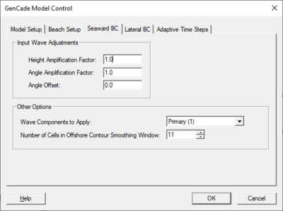
Seaward BC Tab
The following parameters are specified in the seaward boundary condition tab:
- Input Wave Adjustments – This section contains the following options:
- Height Amplification Factor
- Angle Amplification Factor
- Angle Offset
- Wave Components to Apply – options include "Primary (1)" or "Primary & Secondary".
- Number of Cells in Offshore contour Smoothing Window – Default value is 11, but it is suggested that this number range between 11 and 101.
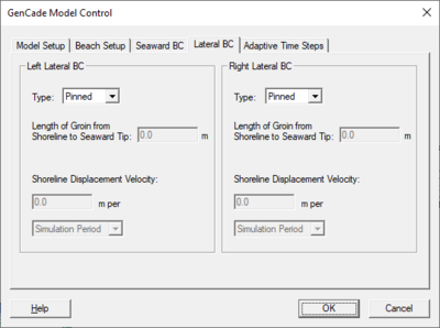
Lateral BC Tab
The following parameters are specified in the lateral boundary condition tab for the left and right lateral boundary condition:
- Type – Determines one of three boundary types:
- "Pinned" – Boundary will not move from the initial shoreline position.
- "Moving" – Represents the amount of shoreline change at a boundary over a specified period of time.
- Shoreline Displacement Velocity – Shoreline can be displaced over the "Simulation Period", "Day", or "Time Step".
- "Gated" – Bounded with a groin. Requires that a groin exist and must be located in cell 1.
- Length of Groin from Shoreline to Seaward Tip
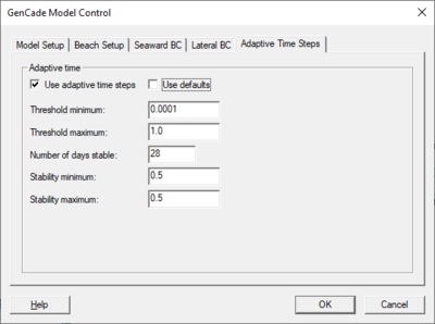
Adaptive Time Steps Tab
The following parameters are specified in the adaptive time steps tab:
- Use adaptive time steps – If turned on, allows the option to use the default values or set custome values.
- Use defaults – If turned on, the default values will be used. If turned off, the following can be set:
- Threshold minimum
- Threshold maximum
- Number of days stable
- Stability minimum
- Stability maximum
Related Topics
SMS – Surface-water Modeling System | ||
|---|---|---|
| Modules: | 1D Grid • Cartesian Grid • Curvilinear Grid • GIS • Map • Mesh • Particle • Quadtree • Raster • Scatter • UGrid |  |
| General Models: | 3D Structure • FVCOM • Generic • PTM | |
| Coastal Models: | ADCIRC • BOUSS-2D • CGWAVE • CMS-Flow • CMS-Wave • GenCade • STWAVE • WAM | |
| Riverine/Estuarine Models: | AdH • HEC-RAS • HYDRO AS-2D • RMA2 • RMA4 • SRH-2D • TUFLOW • TUFLOW FV | |
| Aquaveo • SMS Tutorials • SMS Workflows | ||
