SMS:Convert Elements
Several commands are available to modify the current elements these include:
Add Breakline
The Add Breaklines command from the Elements menu can be executed when at least one nodestring has been selected. This forces element edges along the nodestring line. When this command is performed, elements are sliced along the nodestring to ensure that the edges will conform to the breakline. The elevations of any new nodes are interpolated from the original mesh. All new triangles satisfy the Delauney criterion.
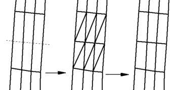
A breakline example is shown. This example has some long, skinny quadrilaterals which will be split across the width. The dotted line in the left part of the figure represents the location of the breakline. When the elements are split, triangles are formed. These can be merged together using the Split/Merge ![]() tool , as shown in the right part of the figure.
tool , as shown in the right part of the figure.
Merge Triangles
The Split/Merge ![]() tool can be used to merge individual pairs of triangles. Doing this manually for large numbers of elements takes a lot of time. The Merge Triangles command from the Elements menu automatically merges a selected set of triangles simultaneously. If no elements are selected when this command is executed, all triangles in the finite element mesh will be processed.
tool can be used to merge individual pairs of triangles. Doing this manually for large numbers of elements takes a lot of time. The Merge Triangles command from the Elements menu automatically merges a selected set of triangles simultaneously. If no elements are selected when this command is executed, all triangles in the finite element mesh will be processed.
This command uses the Merge triangles feature angle specified in Element Option dialog. In order to form quadrilateral elements with the best aspect ratios, SMS starts with a feature angle of ninety degrees and checks for any elements that can be merged. Then, a series of steps are performed, each time lowering the feature angle and checking for elements that can be merged. This ensures that the quadrilaterals which are formed are as close to rectangular as possible. In general, after the automatic merging process is complete, a limited number of triangles will still exist.
Split Quadrilaterals
The Split Quadrilaterals command in the Elements menu is used to split a set of quadrilaterals into triangles. If no elements are selected, all quadrilateral elements in the mesh will be split. The quadrilaterals are split along the shortest diagonal.
Quad8 ↔ Quad9
The Quad8↔Quad9 item from the Elements menu is used to convert between eight- and nine- noded quadrilaterals. FESWMS supports nine-noded quadrilaterals. Both FESWMS and TABS support eight-noded quadrilaterals. If no elements are selected when this command is performed, all elements are converted.
Linear ↔ Quadratic
Linear elements (three node triangles and four node quadrilaterals) can be converted to quadratic elements (six node triangles and eight node quadrilaterals) and vice versa by selecting the Linear ↔ Quadratic item from the Elements menu. A finite element mesh must be made of either all linear elements or all quadratic elements. Linear elements do not have midside nodes while quadratic elements do.
Refine
At times, there is not enough definition in a finite element mesh. The Refine command from the Elements menu splits each of the selected elements into smaller elements. After the selected elements have been refined, SMS automatically creates transitions, from the refined area of higher density to the unrefined area of lower density, using triangular elements. Refine options are set in the Element Options dialog.
Relax
The process of creating and editing a finite element mesh can result in poor quality elements. These elements may have poor interior angles or may violate the area change guideline for adjacent elements. The Relax command from the Elements menu can improve adjacent element areas and interior angles by moving nodes. This command moves nodes to improve the elements shape. Several options are available. Relaxation is an iterative process. The number of iterations performed and other options are specified in the Element Options dialog. If no elements are selected, then the relaxation is performed on all elements in the mesh.
Smooth Nodestring
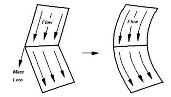
Quadratic elements have a node located at the midpoint of each edge. These nodes are generally referred to as midside nodes. The angular corners resulting from such elements are discontinuous. Such a discontinuity may result in inaccuracy in the numerical model sometimes referred to as a mass loss. Mass loss occurs because water artificially flows out of the mesh.
To minimize the abrupt change in flow direction, element edges can be curved by slightly moving the midside node. This can be done by hand using the Select Mesh Nodes ![]() tool with the nodes unlocked. Moving large numbers of nodes becomes tedious. However, element edges along a selected nodestring can be smoothed by SMS with the Nodestrings | Smooth command.
tool with the nodes unlocked. Moving large numbers of nodes becomes tedious. However, element edges along a selected nodestring can be smoothed by SMS with the Nodestrings | Smooth command.
Normally, element edge smoothness is only a concern along the mesh boundary. However, if the analysis includes regions that become dry, interior boundaries should also be smoothed. To avoid smoothing corners that should be sharp, SMS provides a Smooth nodestring feature angle in the Element Options dialog. A corner will only be smoothed if it is less than the specified angle.
Related Topics
SMS – Surface-water Modeling System | ||
|---|---|---|
| Modules: | 1D Grid • Cartesian Grid • Curvilinear Grid • GIS • Map • Mesh • Particle • Quadtree • Raster • Scatter • UGrid |  |
| General Models: | 3D Structure • FVCOM • Generic • PTM | |
| Coastal Models: | ADCIRC • BOUSS-2D • CGWAVE • CMS-Flow • CMS-Wave • GenCade • STWAVE • WAM | |
| Riverine/Estuarine Models: | AdH • HEC-RAS • HYDRO AS-2D • RMA2 • RMA4 • SRH-2D • TUFLOW • TUFLOW FV | |
| Aquaveo • SMS Tutorials • SMS Workflows | ||

