GMS:Editing a TIN: Difference between revisions
From XMS Wiki
Jump to navigationJump to search
| (3 intermediate revisions by the same user not shown) | |||
| Line 4: | Line 4: | ||
==Editing TIN Vertices== | ==Editing TIN Vertices== | ||
===Creating New TIN Vertices=== | ===Creating New TIN Vertices=== | ||
New vertices can be created using the '''Create Vertices''' tool from the [[GMS:TIN Tool Palette|TIN | New vertices can be created using the '''Create Vertices''' tool from the [[GMS:TIN Tool Palette|TIN tool palette]]. Clicking in the Graphics Window creates a new vertex at the point clicked (vertices can only be created when in '''Plan View'''). The default z value and other parameters governing the creation of new vertices can be set by selecting the '''TIN Settings''' command from the ''TINs'' menu. | ||
===Deleting TIN Vertices=== | ===Deleting TIN Vertices=== | ||
| Line 32: | Line 32: | ||
The density of a TIN can be quickly increased using the '''Uniformly Subdivide TIN''' command in the ''TINs'' menu. A dialog will ask for a subdivision factor and the factor is used to uniformly subdivide the TIN into sub-triangles as shown below: | The density of a TIN can be quickly increased using the '''Uniformly Subdivide TIN''' command in the ''TINs'' menu. A dialog will ask for a subdivision factor and the factor is used to uniformly subdivide the TIN into sub-triangles as shown below: | ||
[[Image:tinsub.png|thumb|center|400 px|TIN (a) | [[Image:tinsub.png|thumb|center|400 px|TIN (a) before and (b) after uniform subdivision.]] | ||
===Subdivide TIN=== | ===Subdivide TIN=== | ||
| Line 42: | Line 42: | ||
*If multiple TINs exist, make sure the TIN is the active TIN. | *If multiple TINs exist, make sure the TIN is the active TIN. | ||
*Convert the TIN to a scatter point set using the '''TIN → Scatter Points''' command in the ''TINs'' menu. | *Convert the TIN to a scatter point set using the '''TIN → Scatter Points''' command in the ''TINs'' menu. | ||
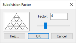
*Subdivide the TIN by selecting the '''Subdivide TIN''' command from the ''TINs'' menu. | *Subdivide the TIN by selecting the '''Subdivide TIN''' command from the ''TINs'' menu and use the ''Subdivision Factor'' dialog. | ||
*Switch to the [[GMS:2D Scatter Point Module|2D Scatter Point module]] and select an interpolation method using the [[GMS:2D Interpolation Options|'''Interp. Options''']] command in the ''Interpolation'' menu. | *Switch to the [[GMS:2D Scatter Point Module|2D Scatter Point module]] and select an interpolation method using the [[GMS:2D Interpolation Options|'''Interp. Options''']] command in the ''Interpolation'' menu. | ||
*Select the to [[GMS:Interpolation Commands|'''Active TIN''']] command from the ''Interpolation'' menu. This creates a new dataset for the selected TIN. | *Select the to [[GMS:Interpolation Commands|'''Active TIN''']] command from the ''Interpolation'' menu. This creates a new dataset for the selected TIN. | ||
| Line 49: | Line 49: | ||
A breakline is a feature line or polyline representing a ridge or some other feature to preserve in a mesh made up of triangular elements. In other words, a breakline is a series of edges to which the triangles should conform to, i.e., not intersect. | A breakline is a feature line or polyline representing a ridge or some other feature to preserve in a mesh made up of triangular elements. In other words, a breakline is a series of edges to which the triangles should conform to, i.e., not intersect. | ||
[[Image:breakline.png|thumb|center|400 px|Breaklines (a) | [[Image:breakline.png|thumb|center|400 px|Breaklines (a) triangulated mesh and breakline. (b) triangulated mesh after the breakline has been processed.]] | ||
Breaklines can be processed using the '''Add Breaklines''' command from the ''Mesh'' menu. Before selecting the command, one or more sequences of nodes defining the breakline(s) should be selected using the '''Select Node Strings''' tool in the [[GMS:2D Mesh Tool Palette|2D Mesh Tool Palette]]. | Breaklines can be processed using the '''Add Breaklines''' command from the ''Mesh'' menu. Before selecting the command, one or more sequences of nodes defining the breakline(s) should be selected using the '''Select Node Strings''' tool in the [[GMS:2D Mesh Tool Palette|2D Mesh Tool Palette]]. | ||


