AHGW:Boundary to DIS Refine Points: Difference between revisions
From XMS Wiki
Jump to navigationJump to search
(Created page with "350px|thumb|right|''Boundary to DIS Refine Points'' dialog The ''Boundary to DIS Refine Point...") |
m (Added a category) |
||
| Line 27: | Line 27: | ||
{{Navbox AHGW}} | {{Navbox AHGW}} | ||
[[Category:AHGW MODFLOW Analyst]] | [[Category:AHGW MODFLOW Analyst]] | ||
[[Category:AHGW Dialogs]] | |||
Revision as of 16:33, 27 August 2019
The Boundary to DIS Refine Points tool is accessed by double-clicking on "![]() Boundary to DIS Refine Points" under the "
Boundary to DIS Refine Points" under the "![]() Features" toolset under the "
Features" toolset under the "![]() MODFLOW Analyst" toolset under the "
MODFLOW Analyst" toolset under the "![]() Arc Hydro Groundwater Tools" toolbox.
Arc Hydro Groundwater Tools" toolbox.
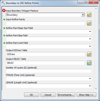
The following fields are available. Required fields are marked with a ![]() icon. Fields marked with a
icon. Fields marked with a ![]() icon may either not be supported or the table doesn't exist.
icon may either not be supported or the table doesn't exist.
- Input Boundary Polygon Feature – Click the
 button to bring up the Input Boundary Polygon Features. dialog in order to specify the name of the boundary polygon features.
  Input Refine Points – Click the
  button to bring up the Input Refine Points dialog in order to specify the wells or other refine points, around which the discretization will be refined.
 Refine Point Base Size Field – A drop-down allowing selection of the field in the refine points containing the base, or minimum size, used in calculating the discretization around the refine points. Used when a bias other than 1.0 is specified.
 Refine Point Bias Field – A drop-down allowing selection of the bias field. This defines how the discretization size varies from one MODFLOW grid cell to the next. For example, a bias of 1.5 causes each cell to be 50% larger than the previous cell. Discretization is calculated by starting with the base size and altering the cell sizes according to the bias until the limit cell size is reached. The remainder of the cell sizes are calculated using the limit size.
 Refine Point Limit Field – A drop-down allowing selection of the field in the refine points containing the limit, or maximum size, used in calculating the discretization around the refine points. Used when a bias other than 1.0 is specified.
- Output DISVars Table – Click the
 button to bring up the Output DISVars Table dialog in order to specify the DISVars table to be created. This table contains variables associated with the MODFLOW DIS file, such as the number of layers, rows and columns in the grid associated with the MODFLOW model.
 - Output DELRC Table – Click the
 button to bring up the Output DELRC Table dialog in order to specify the DELRC table to be created. The DELRC table is used to store the widths (discretization) of the rows and columns in the MODFLOW model.
 - Number of Layers (k) – Optional. An integer value specifying the number of layers to be created in the MODFLOW discretization. By default, one layer will be created.
- ITMUNI (Time Unit) – Optional. The time unit in the MODFLOW discretization. By default, this value is set to undefined. The options include:
- "0 - undefined"
- "1 - seconds"
- "2 - minutes"
- "3 - hours"
- "4 - days"
- "5 - years"
- LENUNI (Length Unit) – Optional. The length unit in the MODFLOW discretization. By default, this value is set to undefined. The options include:
- "0 - undefined"
- "1 - feet"
- "2 - meters"
- "3 - centimeters"

