SMS:TUFLOW Boundary Conditions: Difference between revisions
| (25 intermediate revisions by the same user not shown) | |||
| Line 1: | Line 1: | ||
TUFLOW Boundary conditions may be defined at nodes, arcs, or polygons in a [[SMS:TUFLOW Coverages#Boundary Conditions Coverage| | [[Image:TUFLOW BC Node Attribute.png|thumb|320 px|TUFLOW point or node ''Boundary Conditions'' dialog]] | ||
TUFLOW Boundary conditions may be defined at nodes, arcs, or polygons in a [[SMS:TUFLOW Coverages#Boundary Conditions Coverage|boundary conditions coverage]]. | |||
A boundary condition definition consists of a boundary condition category and one or more boundary condition components. TUFLOW supports the ability to combine multiple definitions into a single curve. Component names must be unique for a project. | |||
A tidal curve and a storm surge curve can both be specified at one location and TUFLOW will sum them to generate a combined water surface elevation curve. | |||
==Boundary Condition Locations== | ==Boundary Condition Locations== | ||
Boundary condition attributes must be assigned to a feature object. The boundary condition type is determined by the feature object being used. | |||
===1D Boundary Conditions at Nodes=== | ===1D Boundary Conditions at Nodes=== | ||
Boundary conditions defined at points are 1D boundary conditions and must be placed at the same location as a 1D boundary node. (See [[SMS:Feature Object Modification: All|Snapping Feature Objects]]) The boundary condition information is specified in the ''BC Node Attributes'' dialog. | Boundary conditions defined at points are 1D boundary conditions and must be placed at the same location as a 1D boundary node. (See [[SMS:Feature Object Modification: All|Snapping Feature Objects]]) The boundary condition information is specified in the ''BC Node Attributes'' dialog. | ||
| Line 13: | Line 18: | ||
* "Wse vs Flow" – Defines a relationship to determine the water surface elevation from a flowrate. The relationship can be specified or TUFLOW can compute it using water surface slope. | * "Wse vs Flow" – Defines a relationship to determine the water surface elevation from a flowrate. The relationship can be specified or TUFLOW can compute it using water surface slope. | ||
All of the boundary condition types for nodes or points include the options described below. | All of the boundary condition types for nodes or points include the [[SMS:TUFLOW_Boundary_Conditions#Options|options]] described below. | ||
===2D Boundary Conditions at Arcs=== | ===2D Boundary Conditions at Arcs=== | ||
Arcs can be used to define 2D | [[Image:TUFLOW Arc BC.png|thumb|320 px|TUFLOW arc ''Boundary Conditions'' dialog]] | ||
Arcs can be used to define 2D boundary conditions applied to the 2D domain. The boundary conditions attributes are specified in the ''Boundary Conditions'' dialog. | |||
Arcs can be assigned any of the following boundary condition types: | Arcs can be assigned any of the following boundary condition types: | ||
* Flow vs Time – Sets the flowrate as a curve through time. | * "No BC" – No boundary condition exists at the location. | ||
* Flow vs Wse – Sets the flowrate based upon a relationship with the water surface elevation. | * "Flow vs Time" – Sets the flowrate as a curve through time. | ||
* Wse vs Time – Sets the water surface elevation as a curve through time. | * "Flow vs Wse" – Sets the flowrate based upon a relationship with the water surface elevation. | ||
* Wse vs Flow – Defines a relationship to determine the water surface elevation from a flowrate. The relationship can be specified or TUFLOW can compute it using water surface slope. | * "Wse vs Time" – Sets the water surface elevation as a curve through time. | ||
* 1D Flow/2D Water Level Connection (HX) – Defines the interface between a 1D and 2D domain. See [[SMS:TUFLOW Combining 1D and 2D Domains|Combining 1D and 2D Domains]]. | * "Wse vs Flow" – Defines a relationship to determine the water surface elevation from a flowrate. The relationship can be specified or TUFLOW can compute it using water surface slope. | ||
* Non-directional Flow vs Time – Defines a flowrate that enters along each cell of the boundary. | * "1D Flow/2D Water Level Connection (HX)" – Defines the interface between a 1D and 2D domain. See [[SMS:TUFLOW Combining 1D and 2D Domains|Combining 1D and 2D Domains]]. Options unique to this type include: | ||
* Non-directional Flow vs Wse – Defines a flowrate that enters along each cell of the boundary based upon a relationship to the water surface elevation. | ** ''Set ZU and ZV elevations to ZC value if lower'' | ||
* Flow Source from 1D model (SX) – Defines an interface between a 1D and 2D domain which is often useful | ** ''Allocate water levels along dry sections'' | ||
[[ | ** ''Set 1D and 2D water levels to same value'' | ||
** ''Adjust ZC to slightly above 1D bed elevation'' | |||
* "Non-directional Flow vs Time" – Defines a flowrate that enters along each cell of the boundary. | |||
* "Non-directional Flow vs Wse" – Defines a flowrate that enters along each cell of the boundary based upon a relationship to the water surface elevation. | |||
* "Flow Source from 1D model (SX)" – Defines an interface between a 1D and 2D domain which is often useful for culverts rather than using the 1D Flow/2D Water Level Connection. Options unique to this type include: | |||
** ''Adjust z elevation in each cell center'' | |||
** ''Do not set 1D water level'' | |||
Most of the boundary condition types for arcs include the [[SMS:TUFLOW_Boundary_Conditions#Options|options]] described below. | |||
===2D Boundary Conditions for Polygons=== | ===2D Boundary Conditions for Polygons=== | ||
[[Image:TUFLOW Polygon BC. | [[Image:TUFLOW Polygon BC.png|thumb|320 px|TUFLOW polygon ''Boundary Conditions'' dialog]] | ||
Polygons can be used to define rainfall applied to 2D domains or to specify active/inactive information for 2D domains. The ''BC Polygon Attributes'' dialog specifies the type of information stored with the polygons. | Polygons can be used to define rainfall applied to 2D domains or to specify active/inactive information for 2D domains. The ''BC Polygon Attributes'' dialog specifies the type of information stored with the polygons. | ||
Polygon boundary conditions can be assigned one of the following three types: | Polygon boundary conditions can be assigned one of the following three types: | ||
* "No BC" – No boundary condition exists at the location. Includes the option ''Set cell node'' which can be set to "Inactive—not in mesh" | * "No BC" – No boundary condition exists at the location. Includes the option ''Set cell node'' which can be set to: | ||
**"Inactive—not in mesh" | |||
**"Inactive—in mesh" | |||
**"Active". | |||
* "Flow/Rainfall over Area" – Defines either an amount of flow entering the polygon (applies to all wet cells or lowest cell if none) or rainfall amounts (applies to all cells in the polygon). | * "Flow/Rainfall over Area" – Defines either an amount of flow entering the polygon (applies to all wet cells or lowest cell if none) or rainfall amounts (applies to all cells in the polygon). | ||
* "Cell Codes" – Specifies whether cells are active or inactive and whether or not they will be included in the mesh output files. | * "Cell Codes" – Specifies whether cells are active or inactive and whether or not they will be included in the mesh output files. | ||
===Convert GIS Rainfall Data to TUFLOW BC Polygons=== | ===Convert GIS Rainfall Data to TUFLOW BC Polygons=== | ||
GIS files containing TUFLOW rainfall data may be imported into SMS and a | GIS files containing TUFLOW rainfall data may be imported into SMS and a boundary condition coverage with the data assigned to polygons will be created. The data for each polygon should be contained in the following columns: | ||
8 STARTYEAR – Year of first data point (integer) | 8 STARTYEAR – Year of first data point (integer) | ||
* STARTMONTH – Month of first data point (integer) | * STARTMONTH – Month of first data point (integer) | ||
| Line 55: | Line 70: | ||
==Events== | ==Events== | ||
[[Image:TUFLOW BC Events.png|thumb|200 px|''TUFLOW BC Event'' dialog]] | |||
Individual boundary conditions can also define multiple events. For example, it can store curves for 10, 50, and 100 year events in the same boundary condition. The event that will be used when running TUFLOW is specified as part of a simulation. | |||
Every boundary condition should be setup for each event that will be used with the boundary condition. The events can be defined by clicking on the '''Add''' [[File:Add button.png]] or '''Remove''' [[File:Remove button.png]] buttons. Event names can be changed by double-clicking on the event. The list of events is common to all the boundary conditions in the project. | Every boundary condition should be setup for each event that will be used with the boundary condition. The events can be defined by clicking on the '''Add''' [[File:Add button.png]] or '''Remove''' [[File:Remove button.png]] buttons. Event names can be changed by double-clicking on the event. The list of events is common to all the boundary conditions in the project. | ||
==Options== | ==Options== | ||
Depending upon the type of boundary condition, there are several additional boundary condition options. Options common to all boundary types include: | Depending upon the type of boundary condition, there are several additional boundary condition options. Options common to all boundary types include: | ||
* ''Override | * ''Override Default Name'' – SMS creates a default unique boundary condition identifier based upon the coverage and id of the arc. Override this value to more easily find boundary condition information in the TUFLOW check, and log files. | ||
* ''Spline Curve'' – If this option is on, TUFLOW will smooth the boundary condition curve using a spline algorithm. This should generally only be used for smooth, cyclic boundary conditions such as a tidal boundary. | * ''Spline Curve'' – If this option is on, TUFLOW will smooth the boundary condition curve using a spline algorithm. This should generally only be used for smooth, cyclic boundary conditions such as a tidal boundary. | ||
* '''Advection Dispersion BC''' – Brings up the [[SMS:TUFLOW_AD#Boundary_Conditions|''Advection Dispersion'']] dialog for TUFLOW AD. Requires having constituents created in the ''TUFLOW 2D Model Control'' dialog. | * '''Advection Dispersion BC''' – Brings up the [[SMS:TUFLOW_AD#Boundary_Conditions|''Advection Dispersion'']] dialog for TUFLOW AD. Requires having constituents created in the ''TUFLOW 2D Model Control'' dialog. | ||
==Related Topics== | ==Related Topics== | ||
| Line 98: | Line 89: | ||
[[Category:TUFLOW|Boundary Conditions]] | [[Category:TUFLOW|Boundary Conditions]] | ||
[[Category:TUFLOW Dialogs]] | [[Category:TUFLOW Dialogs|Bound]] | ||
[[Category:SMS Boundary Conditions|T]] | [[Category:SMS Boundary Conditions|T]] | ||
Latest revision as of 21:13, 23 September 2019
TUFLOW Boundary conditions may be defined at nodes, arcs, or polygons in a boundary conditions coverage.
A boundary condition definition consists of a boundary condition category and one or more boundary condition components. TUFLOW supports the ability to combine multiple definitions into a single curve. Component names must be unique for a project.
A tidal curve and a storm surge curve can both be specified at one location and TUFLOW will sum them to generate a combined water surface elevation curve.
Boundary Condition Locations
Boundary condition attributes must be assigned to a feature object. The boundary condition type is determined by the feature object being used.
1D Boundary Conditions at Nodes
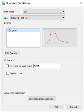
Boundary conditions defined at points are 1D boundary conditions and must be placed at the same location as a 1D boundary node. (See Snapping Feature Objects) The boundary condition information is specified in the BC Node Attributes dialog.
Available boundary condition types for nodes and points include:
- "No BC" – No boundary condition exists at the location.
- "Flow vs Time" – Sets the flowrate as a curve through time.
- "Flow vs Wse" – Sets the flowrate based upon a relationship with the water surface elevation.
- "Wse vs Time" – Sets the water surface elevation as a curve through time.
- "Wse vs Flow" – Defines a relationship to determine the water surface elevation from a flowrate. The relationship can be specified or TUFLOW can compute it using water surface slope.
All of the boundary condition types for nodes or points include the options described below.
2D Boundary Conditions at Arcs
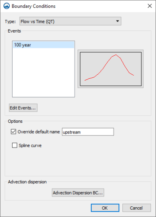
Arcs can be used to define 2D boundary conditions applied to the 2D domain. The boundary conditions attributes are specified in the Boundary Conditions dialog.
Arcs can be assigned any of the following boundary condition types:
- "No BC" – No boundary condition exists at the location.
- "Flow vs Time" – Sets the flowrate as a curve through time.
- "Flow vs Wse" – Sets the flowrate based upon a relationship with the water surface elevation.
- "Wse vs Time" – Sets the water surface elevation as a curve through time.
- "Wse vs Flow" – Defines a relationship to determine the water surface elevation from a flowrate. The relationship can be specified or TUFLOW can compute it using water surface slope.
- "1D Flow/2D Water Level Connection (HX)" – Defines the interface between a 1D and 2D domain. See Combining 1D and 2D Domains. Options unique to this type include:
- Set ZU and ZV elevations to ZC value if lower
- Allocate water levels along dry sections
- Set 1D and 2D water levels to same value
- Adjust ZC to slightly above 1D bed elevation
- "Non-directional Flow vs Time" – Defines a flowrate that enters along each cell of the boundary.
- "Non-directional Flow vs Wse" – Defines a flowrate that enters along each cell of the boundary based upon a relationship to the water surface elevation.
- "Flow Source from 1D model (SX)" – Defines an interface between a 1D and 2D domain which is often useful for culverts rather than using the 1D Flow/2D Water Level Connection. Options unique to this type include:
- Adjust z elevation in each cell center
- Do not set 1D water level
Most of the boundary condition types for arcs include the options described below.
2D Boundary Conditions for Polygons
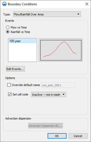
Polygons can be used to define rainfall applied to 2D domains or to specify active/inactive information for 2D domains. The BC Polygon Attributes dialog specifies the type of information stored with the polygons.
Polygon boundary conditions can be assigned one of the following three types:
- "No BC" – No boundary condition exists at the location. Includes the option Set cell node which can be set to:
- "Inactive—not in mesh"
- "Inactive—in mesh"
- "Active".
- "Flow/Rainfall over Area" – Defines either an amount of flow entering the polygon (applies to all wet cells or lowest cell if none) or rainfall amounts (applies to all cells in the polygon).
- "Cell Codes" – Specifies whether cells are active or inactive and whether or not they will be included in the mesh output files.
Convert GIS Rainfall Data to TUFLOW BC Polygons
GIS files containing TUFLOW rainfall data may be imported into SMS and a boundary condition coverage with the data assigned to polygons will be created. The data for each polygon should be contained in the following columns: 8 STARTYEAR – Year of first data point (integer)
- STARTMONTH – Month of first data point (integer)
- STARTDAY – Day of first data point (integer)
- STARTHOUR – Hour of first data point (integer)
- STARTMIN – Minutes of first data point (integer)
- STARTSEC – Seconds of first data point (integer)
- TIMESPAN – Time span between data point in minutes (integer)
- NUMRAINPTS – Number of data points (integer)
- PT0 – Data for the first point (double)
- PT1, PT2,... – Data for each point
When converting GIS rainfall data to TUFLOW rainfall polygons, a prompt will appear to set a reference time. Each rainfall data point will be stored as total mm for each interval of time (hrs) from the reference time.
Events
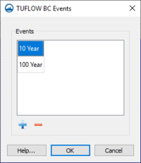
Individual boundary conditions can also define multiple events. For example, it can store curves for 10, 50, and 100 year events in the same boundary condition. The event that will be used when running TUFLOW is specified as part of a simulation.
Every boundary condition should be setup for each event that will be used with the boundary condition. The events can be defined by clicking on the Add ![]() or Remove
or Remove ![]() buttons. Event names can be changed by double-clicking on the event. The list of events is common to all the boundary conditions in the project.
buttons. Event names can be changed by double-clicking on the event. The list of events is common to all the boundary conditions in the project.
Options
Depending upon the type of boundary condition, there are several additional boundary condition options. Options common to all boundary types include:
- Override Default Name – SMS creates a default unique boundary condition identifier based upon the coverage and id of the arc. Override this value to more easily find boundary condition information in the TUFLOW check, and log files.
- Spline Curve – If this option is on, TUFLOW will smooth the boundary condition curve using a spline algorithm. This should generally only be used for smooth, cyclic boundary conditions such as a tidal boundary.
- Advection Dispersion BC – Brings up the Advection Dispersion dialog for TUFLOW AD. Requires having constituents created in the TUFLOW 2D Model Control dialog.
Related Topics
SMS – Surface-water Modeling System | ||
|---|---|---|
| Modules: | 1D Grid • Cartesian Grid • Curvilinear Grid • GIS • Map • Mesh • Particle • Quadtree • Raster • Scatter • UGrid |  |
| General Models: | 3D Structure • FVCOM • Generic • PTM | |
| Coastal Models: | ADCIRC • BOUSS-2D • CGWAVE • CMS-Flow • CMS-Wave • GenCade • STWAVE • WAM | |
| Riverine/Estuarine Models: | AdH • HEC-RAS • HYDRO AS-2D • RMA2 • RMA4 • SRH-2D • TUFLOW • TUFLOW FV | |
| Aquaveo • SMS Tutorials • SMS Workflows | ||


