AHGW:Flow Direction Editor: Difference between revisions
From XMS Wiki
Jump to navigationJump to search
No edit summary |
No edit summary |
||
| (One intermediate revision by the same user not shown) | |||
| Line 1: | Line 1: | ||
[[File:AHGW Flow Direction Editor dialog.png|thumb|250px|right|''Flow Direction Editor'' dialog.]] | [[File:AHGW Flow Direction Editor dialog.png|thumb|250px|right|''Flow Direction Editor'' dialog.]] | ||
The ''Flow Direction Editor'' dialog is accessed by selecting ''Arc Hydro GW'' | '''Flow Direction Generator''' from the Arc Hydro Groundwater toolbar. Raster datasets containing elevation data in the [[AHGW:Arc Hydro Groundwater Data Model|Arc Hydro Groundwater Data Model]] can be used to show the direction of flow in an aquifer. This tool creates a new graphics layer covering the extent of the raster, showing flow direction arrows at a specified interval. | The ''Flow Direction Editor'' dialog is accessed by selecting ''Arc Hydro GW'' | '''Flow Direction Generator''' from the [[AHGW:Arc Hydro Groundwater Toolbar|Arc Hydro Groundwater toolbar]]. Raster datasets containing elevation data in the [[AHGW:Arc Hydro Groundwater Data Model|Arc Hydro Groundwater Data Model]] can be used to show the direction of flow in an aquifer. This tool creates a new graphics layer covering the extent of the raster, showing flow direction arrows at a specified interval. | ||
It has the following options: | It has the following options: | ||
Latest revision as of 23:37, 12 November 2019
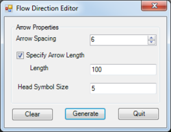
The Flow Direction Editor dialog is accessed by selecting Arc Hydro GW | Flow Direction Generator from the Arc Hydro Groundwater toolbar. Raster datasets containing elevation data in the Arc Hydro Groundwater Data Model can be used to show the direction of flow in an aquifer. This tool creates a new graphics layer covering the extent of the raster, showing flow direction arrows at a specified interval.
It has the following options:
- Arrow Properties section
- Arrow Spacing – Enter an integer value. This is how far apart the flow direction arrows will appear on the generated map.
- Specify Arrow Length – Turn on to enable specifying the length of the arrows.
- Length – If Specify Arrow Length is enabled, enter an integer value for the length of the arrows.
- Head Symbol Size – Enter an integer value for the size of the arrow. A value of "5" is the default and is a good size for general viewability.
- Clear – Clears the generated flow direction arrows on the raster.
- Generate – Generates a set of flow direction arrows for the selected raster.
- Quit – Closes the Flow Direction Editor dialog.
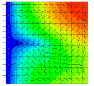
Below is an example of a flow direction map generated using this tool:
| [show] AHGW – Arc Hydro Groundwater Toolbox |
|---|


