GMS:TIN Settings: Difference between revisions
From XMS Wiki
Jump to navigationJump to search
No edit summary |
No edit summary |
||
| (12 intermediate revisions by 3 users not shown) | |||
| Line 1: | Line 1: | ||
{{TIN links}} | {{TIN links}} | ||
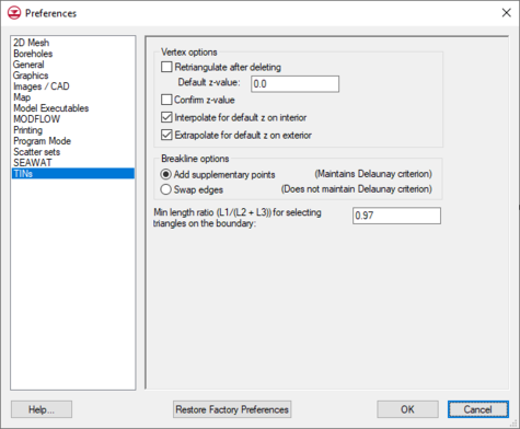
The settings for the TIN module can be found in the ''Preferences'' dialog under the ''TINs'' item. The ''Preferences'' menu can be | The settings for the TIN module can be found in the ''Preferences'' dialog under the ''TINs'' item. The ''Preferences'' menu can be reached by using the '''Preferences...''' command in the ''Edit'' menu and then selecting the ''TINs'' item; or it can be reached by using the '''TIN Settings...''' command in the ''TINs'' menu. The following settings are available: | ||
*''Retriangulate After Deleting'' – If this option is on, the region surrounding the vertex is retriangulated as each vertex is deleted. Otherwise, the triangles adjacent to the vertex are simply deleted. | *''Retriangulate After Deleting'' – If this option is on, the region surrounding the vertex is retriangulated as each vertex is deleted. Otherwise, the triangles adjacent to the vertex are simply deleted. | ||
<!--*''Adjust Boundary to Include Exterior Vertices'' – If this option is on, the boundary of the TIN is changed so that the new vertex becomes part of the TIN if a new point is added outside the active TIN. If the new vertex is in the interior of the active TIN, the vertex is automatically incorporated into the TIN.--> | |||
*''Default Z-Value'' – The default z value is assigned to all new vertices created with the '''Create Vertex''' tool. | |||
*''Default Z-Value'' – The default z value is assigned to all new vertices created with the Create Vertex tool. | |||
*''Confirm Z-Values'' – If this option is on, GMS prompts for a z value each time a new vertex is created. | *''Confirm Z-Values'' – If this option is on, GMS prompts for a z value each time a new vertex is created. | ||
| Line 13: | Line 12: | ||
*''Extrapolate For Default Z On Exterior'' – If this option is on and a new vertex is entered outside the TIN boundary, a default z-value is extrapolated from the TIN to the new vertex. | *''Extrapolate For Default Z On Exterior'' – If this option is on and a new vertex is entered outside the TIN boundary, a default z-value is extrapolated from the TIN to the new vertex. | ||
[[File:PreferencesTINs. | |||
*[[GMS:Editing a TIN#Adding_Breaklines|''Breakline options'']] – The options below define how GMS will add a breakline when the ''TINs'' | ''Advanced'' | [[GMS:Editing a TIN#Adding_Breaklines|'''Add Breakline(s)''']] command is used. | |||
**''Add supplementary points'' – Adds vertices to lines through which breakline passes to create a TIN that will take the breakline into account. Lines will be adjusted to prioritize breaklines. | |||
**''Swap edges'' – Swaps edges to take breaklines into account instead of adding new points. This usually eliminates any lines through which the breakline passes. | |||
*''Minimum length ratio'' – The ratio that GMS will use to determine which triangles to select with the [[GMS:Editing a TIN#Deleting_Triangles|'''Select Boundary Triangles''']] command. | |||
:[[File:PreferencesTINs.png|thumb|none|left|475 px|The ''Preference'' dialog showing the ''TINs'' tab]] | |||
{{Navbox GMS}} | {{Navbox GMS}} | ||
[[Category:TINs]] | [[Category:TINs|Set]] | ||
[[Category:TIN Dialogs]] | [[Category:TIN Dialogs|Set]] | ||
[[Category:Preferences]] | [[Category:Preferences]] | ||
[[Category:GMS Preference Dialogs]] | [[Category:GMS Preference Dialogs]] | ||

