SMS:Floodway Delineation: Difference between revisions
From XMS Wiki
Jump to navigationJump to search
| (6 intermediate revisions by the same user not shown) | |||
| Line 12: | Line 12: | ||
:A mesh or scatter set must be selected. Click '''Select...''' to bring up the ''Select Tree Item'' dialog. It will display any appropriate datasets. | :A mesh or scatter set must be selected. Click '''Select...''' to bring up the ''Select Tree Item'' dialog. It will display any appropriate datasets. | ||
;Smoothing: | [[File:Flow trace example for Floodway.png|thumb|right|The smoother arcs were created using the smoothing options.]] | ||
;Smoothing | |||
:Using a smoothing option turns on flow trace. Flow trace will create smoother floodway extent arcs between each cross section by using the 2D datasets to trace a flow path between each cross section. The image to the right shows a good example of this. The black lines used flow trace, and the greenish lines did not. The option allows for "Complex smoothing", "Simple smoothing", or "No smoothing". | |||
;Enforce banks: | ;Enforce banks | ||
:Turns on or off if the tool will use bank arcs in generating the floodway arcs. Turning this option off will allow for the floodway arcs to be inside of the bank arcs. | |||
===Equal Conveyance Method=== | ===Equal Conveyance Method=== | ||
| Line 47: | Line 50: | ||
;Velocity magnitude: A velocity magnitude dataset must be selected with the "Specify depth and velocity" method. This dataset should the one from under the selected mesh. Click '''Select...''' to bring up the ''Select Tree Item'' dialog. It will display any appropriate datasets. | ;Velocity magnitude: A velocity magnitude dataset must be selected with the "Specify depth and velocity" method. This dataset should the one from under the selected mesh. Click '''Select...''' to bring up the ''Select Tree Item'' dialog. It will display any appropriate datasets. | ||
;Unit Q: A unit Q dataset must be selected with the " | ;Unit Q: A unit Q dataset must be selected with the "Unit discharge method". This dataset should the one from under the selected mesh. Click '''Select...''' to bring up the ''Select Tree Item'' dialog. It will display any appropriate datasets. | ||
;Material coverage | ;Material coverage | ||
:A material coverage can be selected. Click '''Select...''' to bring up the ''Select Tree Item'' dialog. It will display any applicable map coverages. | :A material coverage can be selected. Click '''Select...''' to bring up the ''Select Tree Item'' dialog. It will display any applicable map coverages. | ||
;Threshold: | ;Threshold: Set a threshold for the unit Q discharge. | ||
<!--obsolete | <!--obsolete | ||
| Line 58: | Line 61: | ||
:This is a percentage of the total flow. The initial flux is the percentage of flow that the method will attempt first, as this is an iterative process. The method determines how far in from both sides that vertical walls can be placed and raise the center of flow by the target maximum rise. The method determines the point where the initial flux has been reached from the closest bank, and then simulates a vertical wall and eliminates the flow area between this point and the closest dry bank. The center flow area is increased until the flow area times its velocity accounts for the total flow. | :This is a percentage of the total flow. The initial flux is the percentage of flow that the method will attempt first, as this is an iterative process. The method determines how far in from both sides that vertical walls can be placed and raise the center of flow by the target maximum rise. The method determines the point where the initial flux has been reached from the closest bank, and then simulates a vertical wall and eliminates the flow area between this point and the closest dry bank. The center flow area is increased until the flow area times its velocity accounts for the total flow. | ||
:If the increased depth is lower than the acceptable range, the percentage of flux is increased and the computations repeated. If the increased depth is higher than the acceptable range, the flux percentage is reduced and the computations repeated. If it is within the acceptable range, the method is complete. The default value is "5.0". | :If the increased depth is lower than the acceptable range, the percentage of flux is increased and the computations repeated. If the increased depth is higher than the acceptable range, the flux percentage is reduced and the computations repeated. If it is within the acceptable range, the method is complete. The default value is "5.0". | ||
[[File:Flow trace example for Floodway.png|thumb|right|The smoother arcs were created using flow trace.]] | [[File:Flow trace example for Floodway.png|thumb|right|The smoother arcs were created using flow trace.]] | ||
;Use flow trace | ;Use flow trace | ||
:Checking this box turns on flow trace. Flow trace will create smoother floodway extent arcs between each cross section by using the 2D datasets to trace a flow path between each cross section. The image to the right shows a good example of this. The black lines used flow trace, and the greenish lines did not. | :Checking this box turns on flow trace. Flow trace will create smoother floodway extent arcs between each cross section by using the 2D datasets to trace a flow path between each cross section. The image to the right shows a good example of this. The black lines used flow trace, and the greenish lines did not. | ||
--> | |||
==References== | ==References== | ||
Latest revision as of 20:49, 17 August 2022
Floodway delineation is the process by which an area is marked for use as a floodway. The Federal Emergency Management Agency (FEMA) defines a floodway as follows:
A "Regulatory Floodway" means the channel of a river or other watercourse and the adjacent land areas that must be reserved in order to discharge the base flood without cumulatively increasing the water surface elevation more than a designated height.[1]
Floodway Dialog
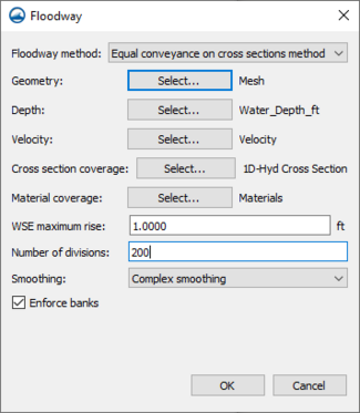
The Floodway tool in SMS is used to delineate approximate floodway extent arcs based on the geometry of the mesh, scatter set, or Cartesian grid used in the project. It is accessed by right-clicking on the 1D hydraulic centerline coverage and selecting Floodway... to bring up the Floodway dialog (right).
- Floodway method
- Option to select method used for floodway delineation: "Equal conveyance on cross sections method" or "Unit discharge method".
- Geometry
- A mesh or scatter set must be selected. Click Select... to bring up the Select Tree Item dialog. It will display any appropriate datasets.
- Smoothing
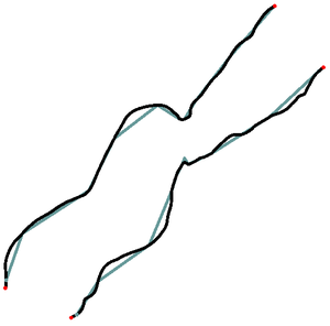
- Using a smoothing option turns on flow trace. Flow trace will create smoother floodway extent arcs between each cross section by using the 2D datasets to trace a flow path between each cross section. The image to the right shows a good example of this. The black lines used flow trace, and the greenish lines did not. The option allows for "Complex smoothing", "Simple smoothing", or "No smoothing".
- Enforce banks
- Turns on or off if the tool will use bank arcs in generating the floodway arcs. Turning this option off will allow for the floodway arcs to be inside of the bank arcs.
Equal Conveyance Method
- Depth
- A depth dataset must be selected. This dataset should the one from under the selected mesh. Click Select... to bring up the Select Tree Item dialog. It will display any appropriate datasets.
- Velocity
- A velocity dataset must be selected. This dataset should the one from under the selected mesh. Click Select... to bring up the Select Tree Item dialog. It will display any appropriate datasets.
- Cross Section Coverage
- A cross section coverage must be selected. Click Select... to bring up the Select Tree Item dialog. It will display any applicable map coverages.
- Material coverage
- A material coverage can be selected. Click Select... to bring up the Select Tree Item dialog. It will display any applicable map coverages.
- WSE Maximum Rise
- The target maximum rise in water surface elevation. FEMA's maximum allowable rise criterion is 1 foot or less. The default value is "1.0".
- Number of Divisions
- This determines the number of vertices and sections created in each arc used to define the floodway.
Unit Discharge Method
- Unit Q method
- Two options are available:
- "Specify depth and velocity" – This option will create a unit Q dataset using depth and velocity.
- "Unit discharge method" – Use to specify the unit Q.
- Depth
- A depth dataset must be selected for the "Specify depth and velocity" method. This dataset should the one from under the selected mesh. Click Select... to bring up the Select Tree Item dialog. It will display any appropriate datasets.
- Velocity magnitude
- A velocity magnitude dataset must be selected with the "Specify depth and velocity" method. This dataset should the one from under the selected mesh. Click Select... to bring up the Select Tree Item dialog. It will display any appropriate datasets.
- Unit Q
- A unit Q dataset must be selected with the "Unit discharge method". This dataset should the one from under the selected mesh. Click Select... to bring up the Select Tree Item dialog. It will display any appropriate datasets.
- Material coverage
- A material coverage can be selected. Click Select... to bring up the Select Tree Item dialog. It will display any applicable map coverages.
- Threshold
- Set a threshold for the unit Q discharge.
References
- ^ "Floodway". Federal Emergency Management Agency. July 18, 2017. https://www.fema.gov/floodway. Retrieved on January 10, 2018.
Related Topics
SMS – Surface-water Modeling System | ||
|---|---|---|
| Modules: | 1D Grid • Cartesian Grid • Curvilinear Grid • GIS • Map • Mesh • Particle • Quadtree • Raster • Scatter • UGrid |  |
| General Models: | 3D Structure • FVCOM • Generic • PTM | |
| Coastal Models: | ADCIRC • BOUSS-2D • CGWAVE • CMS-Flow • CMS-Wave • GenCade • STWAVE • WAM | |
| Riverine/Estuarine Models: | AdH • HEC-RAS • HYDRO AS-2D • RMA2 • RMA4 • SRH-2D • TUFLOW • TUFLOW FV | |
| Aquaveo • SMS Tutorials • SMS Workflows | ||

