Rasters Tools: Difference between revisions
No edit summary |
|||
| (15 intermediate revisions by 4 users not shown) | |||
| Line 1: | Line 1: | ||
{{TOC_right}} | |||
{{ | This article describes tools from the [[SMS:toolbox|SMS toolbox]] that are used to edit, create, and otherwise modify rasters. | ||
==Rasters Tools== | |||
===Bilateral Filter=== | |||
See [https://www.whiteboxgeo.com/manual/wbt_book/available_tools/image_processing_tools_filters.html#BilateralFilter Bilateral Filter] | |||
{{Blend Raster to Edges}} | {{Blend Raster to Edges}} | ||
===Breach Depressions=== | |||
See [https://www.whiteboxgeo.com/manual/wbt_book/available_tools/hydrological_analysis.html#BreachDepressions Breach Depressions] | |||
===Breach Depressions Least Cost=== | |||
See [https://www.whiteboxgeo.com/manual/wbt_book/available_tools/hydrological_analysis.html#BreachDepressionsLeastCost Breach Depressions Least Cost] | |||
{{Clip Raster from Elevation}} | {{Clip Raster from Elevation}} | ||
===Conservative Smoothing Filter=== | |||
See [https://www.whiteboxgeo.com/manual/wbt_book/available_tools/image_processing_tools_filters.html#ConservativeSmoothingFilter Conservative Smoothing Filter] | |||
===D8 Flow Accumulation=== | |||
See [https://www.whiteboxgeo.com/manual/wbt_book/available_tools/hydrological_analysis.html#D8FlowAccumulation D8 Flow Accumulation] | |||
===D8 Flow Directions=== | |||
See [https://www.whiteboxgeo.com/manual/wbt_book/available_tools/hydrological_analysis.html#D8Pointer D8 Flow Directions] | |||
===Edge Preserving Mean Filter=== | |||
See [https://www.whiteboxgeo.com/manual/wbt_book/available_tools/image_processing_tools_filters.html#EdgePreservingMeanFilter Edge Preserving Mean Filter] | |||
{{Edit Elevations}} | {{Edit Elevations}} | ||
{{Extend Raster}} | {{Extend Raster}} | ||
===Extract Streams=== | |||
See [https://www.whiteboxgeo.com/manual/wbt_book/available_tools/stream_network_analysis.html#ExtractStreams Extract Streams] | |||
===Feature Preserving Smoothing=== | |||
See [https://www.whiteboxgeo.com/manual/wbt_book/available_tools/geomorphometric_analysis.html#FeaturePreservingSmoothing Feature Preserving Smoothing] | |||
===Fill Depressions=== | |||
See [https://www.whiteboxgeo.com/manual/wbt_book/available_tools/hydrological_analysis.html#FillDepressions Fill Depressions] | |||
{{Fill Nodata}} | {{Fill Nodata}} | ||
===Flow Accumulation Full Workflow=== | |||
See [https://www.whiteboxgeo.com/manual/wbt_book/available_tools/hydrological_analysis.html#FlowAccumulationFullWorkflow Flow Accumulation Full Workflow] | |||
===Gaussian Filter=== | |||
See [https://www.whiteboxgeo.com/manual/wbt_book/available_tools/image_processing_tools_filters.html#GaussianFilter Gaussian Filter] | |||
{{Interpolate Priority Rasters}} | {{Interpolate Priority Rasters}} | ||
===Isobasins=== | |||
See [https://www.whiteboxgeo.com/manual/wbt_book/available_tools/hydrological_analysis.html#Isobasins Isobasins] | |||
===Mean Filter=== | |||
See [https://www.whiteboxgeo.com/manual/wbt_book/available_tools/image_processing_tools_filters.html#MeanFilter Mean Filter] | |||
{{Merge Elevation Rasters}} | {{Merge Elevation Rasters}} | ||
{{Raster Difference}} | {{Raster Difference}} | ||
{{ | {{Raster from Dataset}} | ||
{{Reproject Raster}} | |||
===Rho8 Flow Accumulation=== | |||
See [https://www.whiteboxgeo.com/manual/wbt_book/available_tools/hydrological_analysis.html#Rho8FlowAccumulation Rho8 Flow Accumulation] | |||
===Rho8 Flow Directions=== | |||
See [https://www.whiteboxgeo.com/manual/wbt_book/available_tools/hydrological_analysis.html#Rho8Pointer Rho8 Flow Directions] | |||
{{Smooth Raster}} | |||
===Strahler Order Basins=== | |||
See [https://www.whiteboxgeo.com/manual/wbt_book/available_tools/hydrological_analysis.html#StrahlerOrderBasins Strahler Order Basins] | |||
===Subbasins=== | |||
See [https://www.whiteboxgeo.com/manual/wbt_book/available_tools/hydrological_analysis.html#Subbasins Subbasins] | |||
{{Trim Raster}} | |||
===Watershed Delineation=== | |||
See [https://www.whiteboxgeo.com/manual/wbt_book/available_tools/hydrological_analysis.html#Watershed Watershed Delineation] | |||
{{WSE Depth Raster from Dataset Tool}} | |||
{{Navbox SMS}} | {{Navbox SMS}} | ||
[[Category:Toolbox]] | [[Category:Toolbox]] | ||
[[Category:Toolbox Rasters]] | |||
Latest revision as of 18:43, 5 June 2024
This article describes tools from the SMS toolbox that are used to edit, create, and otherwise modify rasters.
Rasters Tools
Bilateral Filter
See Bilateral Filter
Blend Raster to Edges
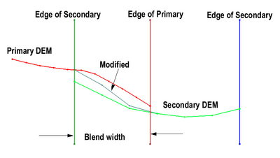
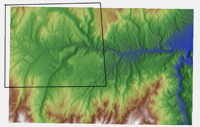
The Blend Raster to Edges tool is intended to facilitate the use of multiple topo/bathy DEMs (potentially from multiple sources) as a source for elevation data on a surface and avoid discontinuities that may exist between the DEMs.
The tool creates a new raster that is a modified version of the raster that is the second argument to the tool. The modified version transition along its active edges from the values in the raster to the values in the primary raster (the first argument).
This tool is intended to be used to pre-condition topo/bathy sources for use in the Interpolate Priority Rasters tool.
Input parameters
- Primary raster – Use the drop-down to select the raster that will be designated as the primary raster.
- Secondary raster – Use the drop-down to select the raster that will be designated as the secondary raster.
- Blend width along edge – Where the edges of the primary and secondary rasters meet, the edges will be blended to the width specified with this option.
Output parameters
- Output raster – Provide a name for the new blended raster.
Current Location in toolbox
Rasters/Blend Raster to Edges
Related Tools
Breach Depressions
Breach Depressions Least Cost
See Breach Depressions Least Cost
Clip Raster from Elevations
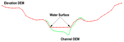
The Clip Raster from Elevations tool creates a new raster (DEM) from a source raster creating invalid data regions in areas where the source raster data are determined to be invalid. To be invalid, the data from the source raster would be either above, or below a provide elevation raster. The side that is invalid is specified as an input parameter.
The Clip Raster from Elevations tool is intended to facilitate the use of multiple topo/bathy DEMs (potentially from multiple sources).
The example of forcing a low flow channel into a DEM illustrates one example of an application of this tool. In this case, it is common for the DEM to have the water surface elevation in regions where the low flow channel exists. These water surface elevation values should not be used in a hydraulic simulation of the area. Instead, channel bed elevations should be supplied. Local survey cross sections are often composed into a channel surface for this purpose. However, due to datum adjustments, time, and roundoff error, the surfaces may have discontinuities. Depending on the situation, the modeler may choose to invalidate the portion of the channel surface that is above the DEM to prevent numerical levees along the edge of the channel.
This tool is intended to be used to pre-condition topo/bathy sources for use in the Interpolate Priority Rasters tool.
Input parameters
- Raster to clip – This option designates the raster which will have elevation values clipped by the elevation raster.
- Elevation raster – This option selects the elevation raster to use.
- Clip elevations above or below elevations raster – Once the raster to clip and elevation raster have been specified, the tool can either clip elevation values either above or below the elevation raster's values.
- "Clip elevations above" – This option removes values that are above the elevation values of the elevation raster.
- "Clip elevations below" – This option removes values that are below the elevation values of the elevation raster.
Output parameters
- Output raster – Enter the name for the new clipped raster.
Current Location in toolbox
Rasters/Blend Raster to Edges
Related Tools
Conservative Smoothing Filter
See Conservative Smoothing Filter
D8 Flow Accumulation
D8 Flow Directions
Edge Preserving Mean Filter
See Edge Preserving Mean Filter
Edit Elevations
The Edit Elevations tool takes point and arc features from a coverage, and burns in their elevation values into a raster, creating a new raster.
Elevation values from points will be assigned to the raster pixels they intersect with. Arc segments will be used to interpolate elevations to intersecting raster pixels, based on the elevation values of nodes and vertices along the arc.
Input Parameters
- Input raster – The raster used to create an edited elevation raster.
- Coverage with elevation values – The coverage containing point and/or arcs with elevation values which will be assigned to the output raster.
Output Parameters
- Output raster – A copy of the input raster, modified with elevation values found in the point and arc features of the coverage.
Current Location in Toolbox
Rasters/Edit Elevations
Extend Raster
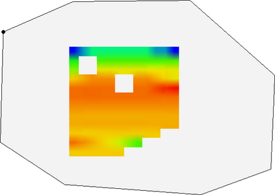
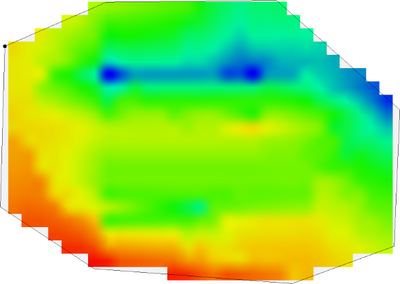
The Extend Raster tool creates a new raster from an existing raster and a coverage with a polygon. The polygons in the coverage extend the active region of the input raster, with the elevation values of the polygons being used to assign elevation values on the raster. Elevation values from the polygon’s nodes and vertices will be used to assign elevation values to the raster on the edges of the polygon. Any gaps or spaces in between the input raster and the polygons in the coverage will be filled in by interpolation. NODATA values inside of the polygon will also be filled in by interpolation.
Input Parameters
- Input raster – The raster for which the active boundary polygon will be created.
- Coverage with polygons – A coverage with a polygon that the input raster will be extended to. The polygon should have elevation values that will be assigned to the output raster.
Output Parameters
- Output raster – The new raster created from the input raster and polygons..
Current Location in Toolbox
Rasters/Bounds to Polygon
Related Tools
- Rasters/Trim Raster
Extract Streams
See Extract Streams
Feature Preserving Smoothing
See Feature Preserving Smoothing
Fill Depressions
See Fill Depressions
Fill Nodata
The Fill Nodata tool creates a new raster by filling in small areas or gaps in a raster where no elevation data exists. The command will interpolate an elevation to raster cells that are classified as "NODATA". The elevation for a NODATA cell is determined by interpolation based on the search radius specified. The command is intended to correct single isolated raster points or a single row/column, and is not intended to create data for large regions of NODATA cells, especially regions on the border of the raster.
Input parameters
- Input raster – The source raster containing the NODATA values.
- Maximum distance (in pixels) to interpolate – Enter a distance used to search out values to interpolate from, to fill in the NODATA values. The default is 100 pixels.
- The number of 3x3 average filter smoothing iterations to run – Enter the number of smoothing iterations to run after the interpolation has been calculated. The default is 0 runs.
Output parameters
- Output raster – Enter a name for the new raster.
Current Location in toolbox
- Rasters/Fill Nodata
Flow Accumulation Full Workflow
See Flow Accumulation Full Workflow
Gaussian Filter
See Gaussian Filter
Interpolate Priority Rasters
The Interpolate Priority Rasters tool creates a new dataset for a selected geometry (UGrid/Mesh2D/Scatter Set) by interpolating from multiple rasters according to a user specified priority. Each source is added to the list in priority order. If a value is not obtained when interpolating from the highest priority source, the tool looks for a value in the next source until either a value is found or all sources are exhausted.
It should be noted that rasters from different sources may have errors or differences from one another for a variety of reasons. Principal causes of incompatibilities between rasters include the changes between the times when each source was gathered, differences in survey methods, and slight adjustments to datums. Large raster differences can result in discontinuities in the surface. These discontinuities can have ramifications on the hydraulic results for simulations of flow over the combined surface.
Observation profiles can be extracted from the surfaces to visualize the differences. If significant differences exist, the Blend Raster to Edges tool and the Clip Raster from Elevations tool can be used to correct them.
It should be noted that the output dataset must be mapped to be the Elevation of the target geometry if that is desired. It is not mapped automatically.
Input parameters
- Grid – Allows selecting the geometry that will receive the interpolated raster values.
- Default dataset – Allows selecting a dataset in the project to use as the default values for interpolation.
- Resample algorithm – Select the method that will be used for interpolation.
- "blinear" – Select to use the linear interpolation method.
- "nearest_neighbor" – Select to use the natural neighbor interpolation method.
- Raster 1 (highest priority) – Select the raster that will be given highest priority during the interpolation process.
- Raster 2 – Select the raster that will be given the next highest priority during the interpolation process.
- Raster n – Additional rasters may be selected and given priority in the order they are selected.
Output parameters
- Output dataset name – Allows setting the name of the new dataset on the specified mesh, UGrid, or scatter set.
Current Location in toolbox
Rasters/Interpolate Priority Rasters
Related Tools
Isobasins
See Isobasins
Mean Filter
See Mean Filter
Merge Elevation Rasters
The Merge Elevation Rasters tool creates a new raster by merging two or more elevation rasters with priority into a new raster. The resolution of the resulting raster will be the resolution of the principal raster (raster 1). The extents of the resulting raster be expanded from the base of the extent defined by raster 1 to include all other rasters.
It should be noted that this operation can result in very large rasters. If a low priority raster has a coarser resolution than the primary raster, it will be super sampled to match the resolution of the primary raster in the areas where this raster extends the domain. This super sampling does not provide new data. For this reason, the Interpolate Priority Rasters tool is recommended ahead of using this operation.
Input parameters
- Raster 1 – Select the first elevation raster to be merged. This raster will be given the highest priority during the merge.
- Blend distance – Enter a distance for the edges of the raster to be blended when merged with another raster. This option can be set for each raster being merged.
- Raster 2 – Select second raster to be merged. This raster will have the next highest priority.
- Raster n – Additional rasters can be added to the merge with lowering priority. These parameters appear as needed. The last field should be left blank
Output parameters
- Merged raster – Enter a name for the new merged raster.
Current Location in toolbox
Rasters/Merge Elevation Rasters
Related Tools
Raster Difference
The Raster Difference tool takes two input rasters, and creates a new raster containing the difference in values between them. One input raster is identified as the base raster, and the other the secondary raster. The rasters do not need to have the same cell size or projection. In order to perform the calculation, a copy of the secondary raster will be resized to align its pixels with those of the base raster, using a cubic resampling algorithm as necessary. The values of each cell in the base raster will be subtracted by the values of each cell in the resampled secondary raster. The resulting output raster will have the same origin and cell size as the base raster. Where data exists in one raster but not in the other, the output raster values will be NODATA values. The tool could be used to compare values of datasets that have been created as rasters using the Dataset to Raster tool.
Input Parameters
- Input base raster – The base raster for which the difference will be calculated.
- Input secondary raster – The raster used to calculate the difference from the base raster.
Output Parameters
- Output raster – The new raster created containing the difference between the base raster and secondary raster. This raster will have the same projection, origin, and cell size as the base raster.
Current Location in Toolbox
- Rasters/Raster Difference
Related Tools
- Rasters/Dataset to Raster
Raster from Dataset
The Raster from Dataset tool creates a raster from a dataset on a geometry (mesh, scatter set, UGrid).
Historically there has been an option in SMS to right-click on a scatter set and convert it to a raster. This tool is more general and can be applied to more geometry types. Because it is included in the toolbox, it can also be accessed outside of the traditional framework of SMS.
Input Parameters
- Dataset – Select the dataset to convert to a raster. (This also selects the associated geometry.)
- Optional template raster – Select a raster from to define the origin and possibly the resolution of the new raster. If a template is not provided, the following arguments are required.
- Pixel size – Enter the pixel resolution size for the new raster.
- If a template raster is selected, the following arguments are required.
- Use raster activity – If this is selected, the new raster will be trimmed to the active region of the template raster.
- Raster template resolution option – Options include:
- Use template raster native resoltion – The resolution of the new raster will match the resolution of the template. (The new raster will have one pixel for each pixel in the template.)
- Specify maximum XY resolution – Specify the resolution of the raster. (Note: if there are inactive regions in the dataset, the resulting raster may be smaller than this specified value.)
- Null value – Enter the null value for the new raster.
- Extrapolation width – Define a buffer width around the dataset geometry. This will extend the new raster in all directions by the specified width. This can be useful if the new raster is going to be used for an interpolation source, but is normally left at the default of 0.0.
Output Parameters
- Output raster – Enter the name for the new raster.
Current Location in Toolbox
Rasters/Raster from Dataset
Reproject Raster
The Reproject Raster tool converts the projection of a raster from its existing projection to another projection. This requires having a projection file containing the new projection/coordinate system for the raster. A new raster file will be generated that contains the raster data with the new projection.
Input Parameters
- Input raster – Select a raster in the project that will be reprojected.
- Output raster .prj file (WKT or PROJ.4 format) – Shows the selected projection file that will be used in assigning a new projection to the reprojected raster.
- Select File – Opens a Select File dialog to use in selecting the projection file.
Output Parameters
- Output raster – Enter a name for new raster that will contain the new projection.
Current Location in Toolbox
Rasters/Reproject Raster
Rho8 Flow Accumulation
Rho8 Flow Directions
Smooth Raster
The Smooth Raster tool is designed to smooth digital elevation models (DEMs) by reducing surface roughness while preserving significant topographic features such as breaks in slope. The tool has the following options:
Input Parameters
- Input raster – Select the raster that will be smoothed.
- Filter size – This determines how many points will be included in the smoothed raster
- Number of interations – This specifies how many passes should be made with the smoothing algorithm.
- Maximum elevation change – This value specifies the maximum allowable elevation change per iteration for each cell.
- Filter ratio (0.0 – 1.0) – The new cell elevation is computed using the original elevation (at the beginning of the iteration not the whole process) and the "blurred" elevation. The filter ratio defines how far the elevation is changed between the original elevation and the "blurred" elevation. A filter ratio of 1.0 would replace the existing elevation with the "blurred" elevation. A filter ratio of 0.0 would be pointless as it wouldn't change the elevations. A filter ratio of 0.5 would give a new elevation that is the average of the original elevation and the blurred elevation.
- Define maximum change from original raster or per iteration – Select an option for defining maximum change:
- "Maximum change defined from original raster"
- "Maximum change defined for each iteration"
Output Paramters
- Output raster – Enter the name for the new smoothed raster.
Current Location in Toolbox
Rasters/Smooth Raster
Related Links
Strahler Order Basins
Subbasins
See Subbasins
Trim Raster
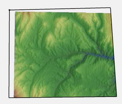
The Trim Raster tool creates a new raster from the raster and coverage selected by the tool. The coverage must contain one or more polygons, which will be used to trim the raster. The polygons can include holes (or interior rings) when used to trim the raster. If more than one polygon is found in the coverage specified, the raster will be trimmed to the polygons, with NODATA values assigned to areas not contained by polygons.
Input Parameters
- Input raster – The raster used to create the trimmed raster.
- Coverage with polygons – The coverage containing one or more polygons used to trim the input raster.
Output parameters
- Output raster – A copy of the input raster, trimmed to the polygon features found in the coverage.
Current Location in toolbox
Rasters/Trim Raster
Related Tools
- Rasters/Extend Raster
Watershed Delineation
WSE/Depth Raster from Dataset
The WSE/Depth Raster from Dataset tool creates a water-surface elevation (WSE) raster and a depth raster from an existing WSE dataset.
Input Parameters
- Elevation Raster – Select a raster in the project that will be used for the WSE raster.
- WSE Dataset – Select a water-surface elevation dataset in the project.
- Number of Pixels to Extrapolate – Define the number of pixels in the resolution of the selected elevation raster to extrapolate to fill in missing data in the raster output. Enter a value of 0 to only use existing WSE dataset values. Extrapolation will only occur inside the mesh boundaries.
Output Parameters
- Output WSE Raster – Enter a name for the new water-surface elevation raster.
- Output Depth Raster – Enter a name for the new flood depth raster.
Current Location in Toolbox
Rasters/WSE/Depth Raster from Dataset
SMS – Surface-water Modeling System | ||
|---|---|---|
| Modules: | 1D Grid • Cartesian Grid • Curvilinear Grid • GIS • Map • Mesh • Particle • Quadtree • Raster • Scatter • UGrid |  |
| General Models: | 3D Structure • FVCOM • Generic • PTM | |
| Coastal Models: | ADCIRC • BOUSS-2D • CGWAVE • CMS-Flow • CMS-Wave • GenCade • STWAVE • WAM | |
| Riverine/Estuarine Models: | AdH • HEC-RAS • HYDRO AS-2D • RMA2 • RMA4 • SRH-2D • TUFLOW • TUFLOW FV | |
| Aquaveo • SMS Tutorials • SMS Workflows | ||
