SMS:BOUSS-2D Graphical Interface: Difference between revisions
| (27 intermediate revisions by the same user not shown) | |||
| Line 2: | Line 2: | ||
== BOUSS-2D Menu == | == BOUSS-2D Menu == | ||
[[File:BOUSS GenerateArcs. | [[File:BOUSS GenerateArcs.png|thumb|250 px|Example of the BOUSS-2D ''Generate Arcs'' dialog.]] | ||
The following menu commands are available in the [[SMS:BOUSS-2D|BOUSS-2D]] simulation [[File:BOUSS2D Simulation Icon.svg|16 px]] right-click menu: | The following menu commands are available in the [[SMS:BOUSS-2D|BOUSS-2D]] simulation [[File:BOUSS2D Simulation Icon.svg|16 px]] right-click menu: | ||
'''Generating Arcs along land boundary''' | ; '''Generating Arcs along land boundary''' : Opens a dialog that will create arcs in a damping or porosity coverage from an existing grid or scatterset. | ||
; '''Generating Arcs along open boundary''' : Opens a dialog that will create arcs in a damping or porosity coverage from an existing grid or scatterset. | |||
Opens a dialog that will create arcs in a damping or porosity coverage from an existing grid or scatterset. | ; [[SMS:BOUSS-2D Calculators|'''Calculators''']] : Brings up a pop up menu to access the''Wave Conditions Calculator'' (see appendix A) as well as the Run-up/Overtopping Estimator. | ||
; [[SMS:BOUSS-2D Probes|'''Probe Manager''']] : Brings up the ''Probe Manager'' to control time series output from the model. | |||
'''Generating Arcs along open boundary''' | ; '''Model Control…''' : | ||
Opens a dialog that will create arcs in a damping or porosity coverage from an existing grid or scatterset. | |||
[[SMS:BOUSS-2D Calculators|'''Calculators''']] | |||
Brings up a pop up menu to access the''Wave Conditions Calculator'' (see appendix A) as well as the Run-up/Overtopping Estimator. | |||
[[SMS:BOUSS-2D Probes|'''Probe Manager''']] | |||
Brings up the ''Probe Manager'' to control time series output from the model. | |||
'''Model Control…''' | |||
Brings up the ''Model Control'' dialog to specificy model parameters. | Brings up the ''Model Control'' dialog to specificy model parameters. | ||
; '''Model Check …''' : Launches the [[SMS:Model Check|Model Check]] to search for common problems. | |||
'''Model Check …''' | ; '''Export BOUSS-2D''' : When the BOUSS-2D files are exported a new directory under the project called “BOUSS-2D” is created. In this directory, the grids will be written to. Also a new directory under the “BOUSS-2D” will be created and it will be the name of the simulation. In this directory, the *.par file(link to Parameter file) can be found. | ||
; '''Run BOUSS-2D''' : Brings up a dialog that allows checking what executable of BOUSS-2D should be run and then runs the model with the currently loaded simulation. As the model runs, a dialog monitors progress of the model and gives the status messages. When the run is complete, the spatial solutions are read in for analysis and visualization. | |||
Launches the [[SMS:Model Check|Model Check]] to search for common problems. | ; '''Save Project, Export, and Run BOUSS-2D''' : Performs the processes of saving the project, exporting BOUSS-2D files, and launching the BOUSS-2D model run. | ||
'''Export BOUSS-2D''' | |||
When the BOUSS-2D files are exported a new directory under the project called “BOUSS-2D” is created. In this directory, the grids will be written to. Also a new directory under the “BOUSS-2D” will be created and it will be the name of the simulation. In this directory, the *.par file(link to Parameter file) can be found. | |||
'''Run BOUSS-2D''' | |||
Brings up a dialog that allows checking what executable of BOUSS-2D should be run and then runs the model with the currently loaded simulation. As the model runs, a dialog monitors progress of the model and gives the status messages. When the run is complete, the spatial solutions are read in for analysis and visualization. | |||
'''Save Project, Export, and Run BOUSS-2D''' | |||
Performs the processes of saving the project, exporting BOUSS-2D files, and launching the BOUSS-2D model run. | |||
===Obsolete Commands=== | ===Obsolete Commands=== | ||
The following commands are no long in use in current versions of SMS but may appear in older versions. | The following commands are no long in use in current versions of SMS but may appear in older versions. | ||
[[SMS:Spectral Energy|'''Spectral Energy''']] | ; [[SMS:Spectral Energy|'''Spectral Energy''']] : Brings up the ''Spectral Energy'' dialog to define/view wave energy spectra. Generally, BOUSS-2D will generate wave conditions internally, but a spectrum may be input. This command also allows visualizing wave spectra that are generated inside of the model. | ||
; '''Assign BC''' : Used to assign damping, porosity, or wave maker conditions along a selected [[SMS:BOUSS-2D Graphical Interface#BC Cell Strings|cell string(s)]]. Using this command will open the ''BOUSS-2D Boundary Conditions'' dialog. | |||
Brings up the ''Spectral Energy'' dialog to define/view wave energy spectra. Generally, BOUSS-2D will generate wave conditions internally, but a spectrum may be input. This command also allows visualizing wave spectra that are generated inside of the model. | ; '''Assign Cell Attributes''' : Selected cells can be defined as land or water | ||
'''Assign BC''' | |||
Used to assign damping, porosity, or wave maker conditions along a selected [[SMS:BOUSS-2D Graphical Interface#BC Cell Strings|cell string(s)]]. Using this command will open the ''BOUSS-2D Boundary Conditions'' dialog. | |||
'''Assign Cell Attributes''' | |||
Selected cells can be defined as land or water | |||
==Polygon Attributes== | ==Polygon Attributes== | ||
| Line 62: | Line 27: | ||
The ''Polygon Attributes'' dialog in BOUSS-2D is used to set the attributes for [[SMS:Feature Objects Types#Polygons|feature polygons]] before converting to a grid. It is reached by double-clicking on a polygon in an BOUSS-2D coverage. Attributes that can be specified for each polygon include: | The ''Polygon Attributes'' dialog in BOUSS-2D is used to set the attributes for [[SMS:Feature Objects Types#Polygons|feature polygons]] before converting to a grid. It is reached by double-clicking on a polygon in an BOUSS-2D coverage. Attributes that can be specified for each polygon include: | ||
* Polygon Type | * Polygon Type | ||
** ''Land '' – Specifies the area as being land cells when the coverage is used to create a grid. | |||
* ''Land '' – Specifies the area as being land cells when the coverage is used to create a grid. | ** ''Ocean'' – Specifies the area as being ocean cells when the coverage is used to create a grid. | ||
* ''Ocean'' – Specifies the area as being ocean cells when the coverage is used to create a grid. | |||
==2D Grid Helps== | ==2D Grid Helps== | ||
| Line 75: | Line 38: | ||
==Wave Maker== | ==Wave Maker== | ||
[[File:BOUSS WaveGeneratorProp. | [[File:BOUSS WaveGeneratorProp.png|thumb|450 px|The ''BOUSS-2D Wave Generator Properties'' dialog.]] A wave maker is created be position a point in a wave maker coverage in the Map module. BOUSS-2D generates waves emanating from this point. Right-clicking on the point and selecting the '''Attributes''' will open the ''BOUSS-2D Wave Generator Properties'' dialog where the properties of the wave are defined. The dialog contains the following three sections: | ||
'''''Wave Simulation Parameters''''' | '''''Wave Simulation Parameters''''' | ||
*Type | * ''Type'' – Options include "Regular", "Irregular Unidirectional", and "Irregular Multidimensional". Selecting "Irregular Multidimensional" will activate the ''Spread option'', ''Standard dev.'', and ''Maximum cutoff'' fields under ''Directional Parameters''. | ||
*Surface Elev. | * ''Surface Elev. Time Series'' – Can be "Synthesize" or "From File". | ||
* ''Spectrum source'' – Can be "From Parameters" or "From File". | |||
*Spectrum source | * ''Random number seed'' – | ||
*Random number seed | * ''Series Duration'' – | ||
*Series | |||
'''''Spectral Parameters''''' | '''''Spectral Parameters''''' | ||
*Type | * ''Type'' – Available when the "Irregular Unidirectional" or "Irregular Multidimensional" type has been selected. Options include: | ||
* | ** "TMA Spectrum (Shallow Water)" | ||
*Wave parameters | ** "JONSWAP Spectrum" | ||
** "Bretschneider (ITTC) Spectrum" | |||
** "Pierson-Moskowitz Spectrum" | |||
** "Ochi-Hubble Double Peak Spectrum" | |||
* ''Option'' – Contains specific options for the "JONSWAP Spectrum" and "Pierson-Moskowitz Spectrum" types. | |||
** "Specify hs and Tp" | |||
** "Specify wind speed and fetch distance" | |||
** "Specify wind speed 19.5 m above sea level" | |||
** "Specify significant wave height" | |||
** "Specify spectral peak period" | |||
*Wave parameters – This spreadsheet allows setting parameters for each wave run. Available parameters depend on the selected type. These options can include: | |||
:{| | |||
|- | |||
| | |||
* ''Wave Height'' | |||
* ''Wave Period'' | |||
* ''Number of Wave Cycles'' | |||
* ''Sig. Wave Height'' | |||
* ''Peak Wave Period'' | |||
| | |||
* ''hs. Low/High Freq.'' | |||
* ''Tp. Low/High Freq.'' | |||
* ''Gamma'' | |||
* ''Wind Speed @ 19.5 m'' | |||
* ''Spectral Peak Period'' | |||
| | |||
* ''Min. Wave Period'' | |||
* ''Max. Wave Period'' | |||
* ''Tidal Offset'' | |||
* ''Storm Duration'' | |||
* ''Rescale Spectrum'' | |||
|} | |||
* '''Add''' – Create an additional wave column in the spreadsheet. | |||
* '''Delete''' – Remove a selected wave column from the spreadsheet. | |||
* '''Calculate Min Period''' – Opens a data selection window where a dataset can be specified. | |||
'''''Directional Parameters''''' | '''''Directional Parameters''''' | ||
*Projection | * ''Projection'' – Can be set to "Oceanographic", "Meteorologic", "Shore Normal", or "Cartesian". | ||
*Spread option | * ''Spread option'' – Options include "Wrapped Normal Distributions" and "Cosine Power Function". This field is only active when the wave simulation ''Type'' is set for "Irregular Multidirectional". | ||
*Standard dev. | * ''Standard dev.'' – Active when the wave simulation ''Type'' is set for "Irregular Multidirectional". | ||
*Maximum cutoff | * ''Maximum cutoff'' – Active when the wave simulation ''Type'' is set for "Irregular Multidirectional". | ||
*Wave angle | * ''Wave angle'' – This is the angle the wave will move from the wave point. | ||
<!--This information is obsolete | <!--This information is obsolete | ||
== Boundary Conditions == | == Boundary Conditions == | ||
Latest revision as of 20:46, 19 July 2019
The BOUSS-2D graphical interface includes tools to assit with creating, editing, and debugging a BOUSS-2D model.
BOUSS-2D Menu
The following menu commands are available in the BOUSS-2D simulation ![]() right-click menu:
right-click menu:
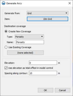
- Generating Arcs along land boundary
- Opens a dialog that will create arcs in a damping or porosity coverage from an existing grid or scatterset.
- Generating Arcs along open boundary
- Opens a dialog that will create arcs in a damping or porosity coverage from an existing grid or scatterset.
- Calculators
- Brings up a pop up menu to access theWave Conditions Calculator (see appendix A) as well as the Run-up/Overtopping Estimator.
- Probe Manager
- Brings up the Probe Manager to control time series output from the model.
- Model Control…
Brings up the Model Control dialog to specificy model parameters.
- Model Check …
- Launches the Model Check to search for common problems.
- Export BOUSS-2D
- When the BOUSS-2D files are exported a new directory under the project called “BOUSS-2D” is created. In this directory, the grids will be written to. Also a new directory under the “BOUSS-2D” will be created and it will be the name of the simulation. In this directory, the *.par file(link to Parameter file) can be found.
- Run BOUSS-2D
- Brings up a dialog that allows checking what executable of BOUSS-2D should be run and then runs the model with the currently loaded simulation. As the model runs, a dialog monitors progress of the model and gives the status messages. When the run is complete, the spatial solutions are read in for analysis and visualization.
- Save Project, Export, and Run BOUSS-2D
- Performs the processes of saving the project, exporting BOUSS-2D files, and launching the BOUSS-2D model run.
Obsolete Commands
The following commands are no long in use in current versions of SMS but may appear in older versions.
- Spectral Energy
- Brings up the Spectral Energy dialog to define/view wave energy spectra. Generally, BOUSS-2D will generate wave conditions internally, but a spectrum may be input. This command also allows visualizing wave spectra that are generated inside of the model.
- Assign BC
- Used to assign damping, porosity, or wave maker conditions along a selected cell string(s). Using this command will open the BOUSS-2D Boundary Conditions dialog.
- Assign Cell Attributes
- Selected cells can be defined as land or water
Polygon Attributes
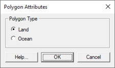
The Polygon Attributes dialog in BOUSS-2D is used to set the attributes for feature polygons before converting to a grid. It is reached by double-clicking on a polygon in an BOUSS-2D coverage. Attributes that can be specified for each polygon include:
- Polygon Type
- Land – Specifies the area as being land cells when the coverage is used to create a grid.
- Ocean – Specifies the area as being ocean cells when the coverage is used to create a grid.
2D Grid Helps
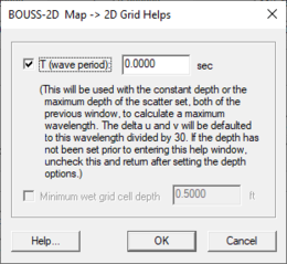
When creating a Cartesian grid from a BOUSS-2D map coverage, the Map → 2D Grid dialog contains and addition option: the Grid Helps button at the bottom of the dialog. Clicking the Grid Helps button will open the BOUSS-2D Map → 2D Grid Helps dialog. An appropriate cell size depends on the wavelength of the waves being modeled. Use the BOUSS-2D Map → 2D Grid Helps dialog to get help with determining a cell size.
Model Control
The BOUSS-2D Model Control dialog is used to setup the options that apply to the simulation as a whole. These options include time controls, run types, output options, global parameters, print options and other global settings.
Wave Maker
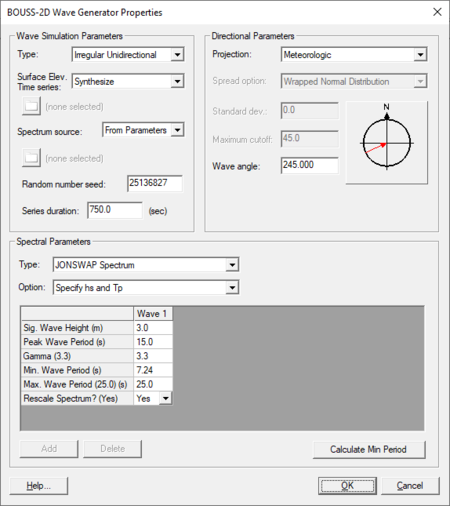
A wave maker is created be position a point in a wave maker coverage in the Map module. BOUSS-2D generates waves emanating from this point. Right-clicking on the point and selecting the Attributes will open the BOUSS-2D Wave Generator Properties dialog where the properties of the wave are defined. The dialog contains the following three sections:
Wave Simulation Parameters
- Type – Options include "Regular", "Irregular Unidirectional", and "Irregular Multidimensional". Selecting "Irregular Multidimensional" will activate the Spread option, Standard dev., and Maximum cutoff fields under Directional Parameters.
- Surface Elev. Time Series – Can be "Synthesize" or "From File".
- Spectrum source – Can be "From Parameters" or "From File".
- Random number seed –
- Series Duration –
Spectral Parameters
- Type – Available when the "Irregular Unidirectional" or "Irregular Multidimensional" type has been selected. Options include:
- "TMA Spectrum (Shallow Water)"
- "JONSWAP Spectrum"
- "Bretschneider (ITTC) Spectrum"
- "Pierson-Moskowitz Spectrum"
- "Ochi-Hubble Double Peak Spectrum"
- Option – Contains specific options for the "JONSWAP Spectrum" and "Pierson-Moskowitz Spectrum" types.
- "Specify hs and Tp"
- "Specify wind speed and fetch distance"
- "Specify wind speed 19.5 m above sea level"
- "Specify significant wave height"
- "Specify spectral peak period"
- Wave parameters – This spreadsheet allows setting parameters for each wave run. Available parameters depend on the selected type. These options can include:
- Wave Height
- Wave Period
- Number of Wave Cycles
- Sig. Wave Height
- Peak Wave Period
- hs. Low/High Freq.
- Tp. Low/High Freq.
- Gamma
- Wind Speed @ 19.5 m
- Spectral Peak Period
- Min. Wave Period
- Max. Wave Period
- Tidal Offset
- Storm Duration
- Rescale Spectrum
- Add – Create an additional wave column in the spreadsheet.
- Delete – Remove a selected wave column from the spreadsheet.
- Calculate Min Period – Opens a data selection window where a dataset can be specified.
Directional Parameters
- Projection – Can be set to "Oceanographic", "Meteorologic", "Shore Normal", or "Cartesian".
- Spread option – Options include "Wrapped Normal Distributions" and "Cosine Power Function". This field is only active when the wave simulation Type is set for "Irregular Multidirectional".
- Standard dev. – Active when the wave simulation Type is set for "Irregular Multidirectional".
- Maximum cutoff – Active when the wave simulation Type is set for "Irregular Multidirectional".
- Wave angle – This is the angle the wave will move from the wave point.
Running the Model
The BOUSS-2D files are written automatically with the SMS project file or can be saved separately using the File | Save BOUSS-2D or File | Save As menu commands. See BOUSS-2D Files for more information on the files used for the BOUSS-2D run.
BOUSS-2D can be launched from SMS using the Run BOUSS-2D right-click menu command. A check of some of the common problems called the Model Checker is done each time the model is launched, or by selecting the Model Check right-click menu command.
Related Topics
SMS – Surface-water Modeling System | ||
|---|---|---|
| Modules: | 1D Grid • Cartesian Grid • Curvilinear Grid • GIS • Map • Mesh • Particle • Quadtree • Raster • Scatter • UGrid |  |
| General Models: | 3D Structure • FVCOM • Generic • PTM | |
| Coastal Models: | ADCIRC • BOUSS-2D • CGWAVE • CMS-Flow • CMS-Wave • GenCade • STWAVE • WAM | |
| Riverine/Estuarine Models: | AdH • HEC-RAS • HYDRO AS-2D • RMA2 • RMA4 • SRH-2D • TUFLOW • TUFLOW FV | |
| Aquaveo • SMS Tutorials • SMS Workflows | ||


