GMS:Building a FEMWATER Model: Difference between revisions
From XMS Wiki
Jump to navigationJump to search
| (2 intermediate revisions by the same user not shown) | |||
| Line 17: | Line 17: | ||
==FEMWATER Direct Approach== | ==FEMWATER Direct Approach== | ||
For models with simple geometry and boundary conditions, the entire model can be constructed using the tools and commands in the 3D Mesh module. With this approach, the editing of the FEMWATER data is performed directly on the nodes and elements of the mesh. The first step is to create a 3D mesh covering the model domain using the mesh building tools in the 3D Mesh module. The boundary conditions and source/sink terms are then assigned by [[GMS:3D Mesh Tool Palette|selecting nodes]], [[GMS:3D Mesh Tool Palette|elements]], and [[GMS:3D Mesh Tool Palette|element faces]] and assigning values directly to the selected objects. The model is then saved and FEMWATER is launched. | For models with simple geometry and boundary conditions, the entire model can be constructed using the tools and commands in the 3D Mesh module. With this approach, the editing of the FEMWATER data is performed directly on the nodes and elements of the mesh. The first step is to create a 3D mesh covering the model domain using the mesh building tools in the 3D Mesh module. The boundary conditions and source/sink terms are then assigned by [[GMS:3D Mesh Tool Palette|selecting nodes]], [[GMS:3D Mesh Tool Palette|elements]], and [[GMS:3D Mesh Tool Palette|element faces]] and assigning values directly to the selected objects. The model is then saved and FEMWATER is launched. | ||
| Line 26: | Line 24: | ||
:The tools provided in GMS for constructing a 3D finite element mesh are provided in the 3D Mesh Module. When constructing a mesh for FEMWATER, there are a few important guidelines that should be considered. These guidelines are described in Chapter 3 of the FEMWATER reference manual. | :The tools provided in GMS for constructing a 3D finite element mesh are provided in the 3D Mesh Module. When constructing a mesh for FEMWATER, there are a few important guidelines that should be considered. These guidelines are described in Chapter 3 of the FEMWATER reference manual. | ||
:The most efficient method for constructing a 3D mesh for FEMWATER is to use the conceptual model approach. The FEMWATER conceptual model can be used to automatically build a 2D mesh that matches the model boundaries and is refined around wells. This mesh can then be [[GMS: | :The most efficient method for constructing a 3D mesh for FEMWATER is to use the conceptual model approach. The FEMWATER conceptual model can be used to automatically build a 2D mesh that matches the model boundaries and is refined around wells. This mesh can then be [[GMS:Building_a_FEMWATER_Model#Build_a_3D_Finite_Element_Mesh|extruded into a 3D mesh]]. | ||
:Solids can also be used to make a structured mesh. This is accomplished with the [[GMS:Solids to Layered Mesh|'''Solids → Layered Mesh''']] command in the ''Solids'' menu. | :Solids can also be used to make a structured mesh. This is accomplished with the [[GMS:Solids to Layered Mesh|'''Solids → Layered Mesh''']] command in the ''Solids'' menu. | ||
| Line 37: | Line 35: | ||
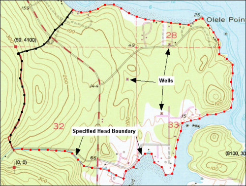
The conceptual model approach utilizes [[GMS:Feature Objects|feature objects]] in the [[GMS:Map Module|Map module]]. A FEMWATER conceptual model is created in the Map module and feature objects are used to create a high level representation of the site being modeled. The figure below shows a sample conceptual model. | The conceptual model approach utilizes [[GMS:Feature Objects|feature objects]] in the [[GMS:Map Module|Map module]]. A FEMWATER conceptual model is created in the Map module and feature objects are used to create a high level representation of the site being modeled. The figure below shows a sample conceptual model. | ||
[[Image:samp_map.png|thumb| | :[[Image:samp_map.png|thumb|none|500 px|Sample FEMWATER conceptual model]] | ||
===Two Step Process=== | ===Two Step Process=== | ||
| Line 43: | Line 41: | ||
A FEMWATER conceptual model is used to build a numerical model using a two step process. | A FEMWATER conceptual model is used to build a numerical model using a two step process. | ||
#In the first step, a 3D mesh is created. This can be done by using the feature objects in conjunction [[GMS: | #In the first step, a 3D mesh is created. This can be done by using the feature objects in conjunction [[GMS:Building_a_FEMWATER_Model#Build_a_3D_Finite_Element_Mesh|with a set of TINs to build a 3D mesh]] or a solid can be converted to a layered 3D mesh using the [[GMS:Solids to Layered Mesh|'''Solids → Layered Mesh''']] command. | ||
#In the second step, the boundary conditions and recharge values assigned to the feature objects are automatically assigned to the appropriate nodes and element faces of the 3D mesh using the ''Feature Objects'' | '''Map → FEMWATER''' command. | #In the second step, the boundary conditions and recharge values assigned to the feature objects are automatically assigned to the appropriate nodes and element faces of the 3D mesh using the ''Feature Objects'' | '''Map → FEMWATER''' command. | ||


