SMS:Snapping: Difference between revisions
| (15 intermediate revisions by the same user not shown) | |||
| Line 2: | Line 2: | ||
==Snapping Feature Objects within a Coverage== | ==Snapping Feature Objects within a Coverage== | ||
Within a coverage, the Clean tool can be used to connect nodes of arcs together. This can fix cases where the nodes are not quite touching and thus preventing a fully enclosed arc for a polygon. | Within a coverage, the [[SMS:Feature_Object_Modification:_All#Clean|''Clean'']] tool can be used to connect nodes of arcs together. This can fix cases where the nodes are not quite touching and thus preventing a fully enclosed arc for a polygon. | ||
==Snapping Feature Objects to Another Coverage== | ==Snapping Feature Objects to Another Coverage== | ||
In some situations, it is necessary to create feature objects that line up with feature objects on another coverage. | In some situations, it is necessary to create feature objects that line up with feature objects on another coverage. When getting close to the nodes in the other coverage, there should appear red crosshairs. This indicates that the node will snap to the existing node in the other coverage. | ||
If the red crosshairs do not appear, hitting ''S'' on the keyboard will activate this snapping functionality or turn on in the ''Map'' tab of the [[SMS:Preferences#Map|''SMS Preferences'']] dialog. | |||
[[File:Snap crosshairs.png|thumb|none|380 px|Crosshairs displayed when snapping]] | |||
==Snap Preview of Feature Objects to a Geometry== | ==Snap Preview of Feature Objects to a Geometry== | ||
The Snap Preview option allows seeing how feature objects on a coverage will align with a the elements or cells on a geometry during a model run. | The [[SMS:Map Module Display Options|Snap Preview]] option allows seeing how feature objects on a coverage will align with a the elements or cells on a geometry during a model run. This is primarily used with SRH-2D model simulations. | ||
Model parameters assigned to feature objects are applied to the model by “snapping” them to the nearest mesh element edges. Model parameters such as boundary conditions and material properties are assigned to feature objects. Linking coverages to mesh in an SRH-2D simulation causes the parameters to be applied to the linked mesh. Parameters specified for boundary condition arcs or arc defining polygon boundaries are always applied (snapped) to the nearest mesh element edges instead of at the arc locations. Polygons snap to cover all elements with centroids contained inside the poylgon. If an element's centroid happens to fall on the boundary of a polygon, the elements will be classified as outside of the polygon area. | |||
Snapping is not available until a model simulation exists and both the coverages with the feature objects and the mesh are linked to the simulation. | |||
The element edges that will have the parameters from linked feature objects can be viewed by right-clicking on the simulation and using the '''Generate Snap Preview''' command. This option is only available once the coverages and a mesh are linked to a simulation. After using the '''Generate Snap Preview''' command, a window may appear as the preview is generated. When completed, the a number of preview objects will appear in the Project Explorer under the simulation. These preview objects can include: | |||
* Boundary condition coverage preview | |||
*Monitor coverage preview | |||
*Material coverage preview. | |||
The preview objects in the Project Explorer can be turned on or off. Right-click on a preview object allows selecting a '''Display Options''' command to access display options for the snap preview. The display options match those for the coverage the preview object was generated from. | |||
Snap previews are displayed right on the mesh. As an example, this means the material snapping is displayed on a cell by cell basis right on the surface of the cell. The figure below illustrate an example of how the parameters for boundary condition arcs and material polygons would be snapped to a mesh for an SRH-2D model run. | |||
[[File:Snapping Examples.png|thumb|none|550 px|Snap Preview examples]] | |||
The snap preview object is only generated after using the '''Generate Snap Preview''' command. When the display is updated, the snap preview is not updated until the command is used again. This is avoid slowing down the display rate in the Graphics Window. | |||
In SMS 13.0, the element edges that will have the parameters from linked feature objects were viewed by turning on the ''Snap Preview'' in the ''Display Options'' dialog under the ''Map'' section. This option was only available once the coverages and a mesh are linked to a simulation. Turning on the ''Snap Preview'' display option in SMS showed a preview of how the feature objects are “snapped” to the element edges using dotted lines to represent the snapped element edges. | |||
==Related Topics== | |||
* [[SMS:Map Module Display Options|Map Module Display Options]] | |||
Latest revision as of 22:56, 4 December 2020
The term "snapping" in SMS can refer to a couple different situations in SMS. All involve the use of the Map module and how feature objects align with other objects.
Snapping Feature Objects within a Coverage
Within a coverage, the Clean tool can be used to connect nodes of arcs together. This can fix cases where the nodes are not quite touching and thus preventing a fully enclosed arc for a polygon.
Snapping Feature Objects to Another Coverage
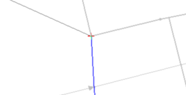
In some situations, it is necessary to create feature objects that line up with feature objects on another coverage. When getting close to the nodes in the other coverage, there should appear red crosshairs. This indicates that the node will snap to the existing node in the other coverage.
If the red crosshairs do not appear, hitting S on the keyboard will activate this snapping functionality or turn on in the Map tab of the SMS Preferences dialog.
Snap Preview of Feature Objects to a Geometry
The Snap Preview option allows seeing how feature objects on a coverage will align with a the elements or cells on a geometry during a model run. This is primarily used with SRH-2D model simulations.
Model parameters assigned to feature objects are applied to the model by “snapping” them to the nearest mesh element edges. Model parameters such as boundary conditions and material properties are assigned to feature objects. Linking coverages to mesh in an SRH-2D simulation causes the parameters to be applied to the linked mesh. Parameters specified for boundary condition arcs or arc defining polygon boundaries are always applied (snapped) to the nearest mesh element edges instead of at the arc locations. Polygons snap to cover all elements with centroids contained inside the poylgon. If an element's centroid happens to fall on the boundary of a polygon, the elements will be classified as outside of the polygon area.
Snapping is not available until a model simulation exists and both the coverages with the feature objects and the mesh are linked to the simulation.
The element edges that will have the parameters from linked feature objects can be viewed by right-clicking on the simulation and using the Generate Snap Preview command. This option is only available once the coverages and a mesh are linked to a simulation. After using the Generate Snap Preview command, a window may appear as the preview is generated. When completed, the a number of preview objects will appear in the Project Explorer under the simulation. These preview objects can include:
- Boundary condition coverage preview
- Monitor coverage preview
- Material coverage preview.
The preview objects in the Project Explorer can be turned on or off. Right-click on a preview object allows selecting a Display Options command to access display options for the snap preview. The display options match those for the coverage the preview object was generated from.
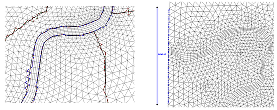
Snap previews are displayed right on the mesh. As an example, this means the material snapping is displayed on a cell by cell basis right on the surface of the cell. The figure below illustrate an example of how the parameters for boundary condition arcs and material polygons would be snapped to a mesh for an SRH-2D model run.
The snap preview object is only generated after using the Generate Snap Preview command. When the display is updated, the snap preview is not updated until the command is used again. This is avoid slowing down the display rate in the Graphics Window.
In SMS 13.0, the element edges that will have the parameters from linked feature objects were viewed by turning on the Snap Preview in the Display Options dialog under the Map section. This option was only available once the coverages and a mesh are linked to a simulation. Turning on the Snap Preview display option in SMS showed a preview of how the feature objects are “snapped” to the element edges using dotted lines to represent the snapped element edges.
Related Topics
SMS – Surface-water Modeling System | ||
|---|---|---|
| Modules: | 1D Grid • Cartesian Grid • Curvilinear Grid • GIS • Map • Mesh • Particle • Quadtree • Raster • Scatter • UGrid |  |
| General Models: | 3D Structure • FVCOM • Generic • PTM | |
| Coastal Models: | ADCIRC • BOUSS-2D • CGWAVE • CMS-Flow • CMS-Wave • GenCade • STWAVE • WAM | |
| Riverine/Estuarine Models: | AdH • HEC-RAS • HYDRO AS-2D • RMA2 • RMA4 • SRH-2D • TUFLOW • TUFLOW FV | |
| Aquaveo • SMS Tutorials • SMS Workflows | ||

