User:Jcreer/TUFLOW FV for SMS 13.2: Difference between revisions
| (102 intermediate revisions by 2 users not shown) | |||
| Line 22: | Line 22: | ||
== SMS Interface == | == SMS Interface == | ||
The TUFLOW FV engine is interfaced in SMS through the [[SMS: | The TUFLOW FV engine is interfaced in SMS through the dynamic model interface. It makes use of the SMS [[SMS:Simulations|simulation]] workflow. | ||
===TUFLOW FV Coverages=== | ===TUFLOW FV Coverages=== | ||
| Line 80: | Line 80: | ||
[[File:TUFLOWFV MC General.png|thumb|300 px|The ''General'' tab of the ''TUFLOW FV Model Control'' dialog]] | [[File:TUFLOWFV MC General.png|thumb|300 px|The ''General'' tab of the ''TUFLOW FV Model Control'' dialog]] | ||
The ''General'' tab of the ''TUFLOW FV Model Control'' dialog contains the following options: | The ''General'' tab of the ''TUFLOW FV Model Control'' dialog contains the following options: | ||
*''Define spatial order'' – | *''Define spatial order'' – Option to define horizontal spatial scheme. | ||
**''Horizontal'' – Select "1st" order scheme or "2nd" order scheme. | **''Horizontal'' – Select "1st" order scheme or "2nd" order scheme. | ||
*Define display interval – | ***"1st" – Sets the simulation to use a 1<sup>st</sup> order scheme. This can be used when there is not a significant difference between the results for 1<sup>st</sup> and 2<sup>nd</sup> order schemes. It's also generally used for the beginning stages of most model development. | ||
**Display interval'' | ***"2nd" – Sets the simulation to use a 2<sup>nd</sup> order scheme. This is used when a significant difference is noticed between 1<sup>st</sup> and 2<sup>nd</sup> order schemes. It's usually tested in more advanced stages of model development. Fast-changing flow conditions or high gradients in conserved variables might warrant or necessitate use of this spatial scheme. | ||
*''Define display interval'' – Option to set the interval in seconds at which time step information will be displayed to the (log and terminal window??). | |||
**''Display interval'' – Sets the interval in seconds for the display of time step information. | |||
*''Define hardware solver'' – Option to enable computing through the CPU or the GPU. Can produce slight differences in results. | *''Define hardware solver'' – Option to enable computing through the CPU or the GPU. Can produce slight differences in results. | ||
**"CPU" – Calculations will use the "Central Processing Unit". | **"CPU" – Calculations will use the "Central Processing Unit". | ||
**"GPU" – Calculations will use the "Graphical Processing Unit". Using GPU with TUFLOW | **"GPU" – Calculations will use the "Graphical Processing Unit". Using GPU with TUFLOW | ||
***''Device ID'' – Option to select which GPU device is used for computers or GPUs with multiple CUDA enabled GPU cards. | ***''Device ID'' – Option to select which GPU device is used for computers or GPUs with multiple CUDA enabled GPU cards. | ||
*''Warn on projection mismatch of GIS inputs'' – | *''Warn on projection mismatch of GIS inputs'' – Sets the program to warn if GIS inputs are not all in the same projection. | ||
*''Tutorial model'' – (Allows simulation of the TUFLOW Tutorial Models without the need for a TUFLOW license.??) | *''Tutorial model'' – (Allows simulation of the TUFLOW Tutorial Models without the need for a TUFLOW license.??) | ||
{{-}} | {{-}} | ||
| Line 97: | Line 99: | ||
*''Simulation time'' | *''Simulation time'' | ||
**''Use ISODate'' – Option to use ISODate format which requires data be input in the form dd/mm/yyyy HH:MM:SS. If left off, default time format is hours. | **''Use ISODate'' – Option to use ISODate format which requires data be input in the form dd/mm/yyyy HH:MM:SS. If left off, default time format is hours. | ||
**Reference time – Will set simulation reference time. Times set for starting and ending have reference to this time. This can affect output times when processing and visualizing results from certain programs. | **''Reference time'' – Will set simulation reference time. Times set for starting and ending have reference to this time. This can affect output times when processing and visualizing results from certain programs. | ||
**Starting time – Will set simulation start time. | **''Starting time'' – Will set simulation start time. | ||
**Ending time – Will set simulation end time. | **''Ending time'' – Will set simulation end time. | ||
*Time step limits | *''Time step limits'' | ||
**CFL – Sets the Courant-Friedrichs-Lewy condition. ((This is a control number that gives the model...???)). Can be no larger than one since this is the theoretical stability limit. Often, inputting a value lower than one ensures greater model stability. | **''CFL'' – Sets the Courant-Friedrichs-Lewy condition. ((This is a control number that gives the model...???)). Can be no larger than one since this is the theoretical stability limit. Often, inputting a value lower than one ensures greater model stability. | ||
**Min time step(s) – | **''Min time step(s)'' – Specifies minimum variable time step allowed according to CFL stability criterion. | ||
**Max time step(s) – | **''Max time step(s)'' – Specifies maximum variable time step allowed according to CFL stability criterion. | ||
{{-}} | {{-}} | ||
| Line 109: | Line 111: | ||
[[File:TUFLOWFV MC Global.png|thumb|300 px|The ''Global parameters'' tab of the ''TUFLOW FV Model Control'' dialog]] | [[File:TUFLOWFV MC Global.png|thumb|300 px|The ''Global parameters'' tab of the ''TUFLOW FV Model Control'' dialog]] | ||
The ''Global parameters'' tab of the ''TUFLOW FV Model Control'' dialog contains the following options: | The ''Global parameters'' tab of the ''TUFLOW FV Model Control'' dialog contains the following options: | ||
*Define bottom drag model – Option to specify bottom drag model for the simulation. The bottom drag model will be used to describe | *''Define bottom drag model'' – Option to specify bottom drag model for the simulation. The bottom drag model will be used to describe bed boundary resistance in the simulation. The same bottom drag model will be used for every calculation that uses it. | ||
**Method – Option to set bottom drag model to use "Manning" or "KS". | **''Method'' – Option to set bottom drag model to use "Manning" or "KS". | ||
***"Manning" – Uses the Manning model and requires a Manning's ''n'' coefficient | ***"Manning" – Uses the Manning model and requires a Manning's ''n'' coefficient | ||
****Manning's n coefficient – Sets the Manning's ''n'' coefficient. | ****''Manning's n coefficient'' – Sets the Manning's ''n'' coefficient. | ||
***"KS" – | ***"KS" – Uses a model that assumes a log-law velocity profile and requires specification of a surface roughness length-scale. | ||
****Nikuradse roughness – Sets the Nikuradse roughness for the bottom drag model. | ****''Nikuradse roughness'' – Sets the Nikuradse roughness for the bottom drag model. | ||
*Horizontal mixing model – | *''Horizontal mixing model'' – Defines horizontal mixing eddy viscosity calculation according to options in drop-down menu. ((In TUFLOW FV documentation it's called momentum mixing model??)). | ||
**"None" – Will not represent horizontal momentum mixing. | **"None" – Will not represent horizontal momentum mixing. | ||
**"Constant" – Option to globally define a specific constant eddy viscosity | **"Constant" – Option to globally define a specific constant eddy viscosity. | ||
***Global horizontal eddy viscosity – Specifies the constant eddy viscosity | ***''Global horizontal eddy viscosity'' – Specifies the constant eddy viscosity for the entire simulation. | ||
**"Smagorinsky" – The horizontal eddy viscosity will be calculated according to the Smagorinsky model which sets the diffusivity proportional to the local strain rate. Requires specification of global horizontal eddy viscosity coefficient. | **"Smagorinsky" – The horizontal eddy viscosity will be calculated according to the Smagorinsky model which sets the diffusivity proportional to the local strain rate. Requires specification of global horizontal eddy viscosity coefficient. | ||
***Global horizontal eddy viscosity coefficient – Sets the Smagorinsky coefficient for the horizontal mixing eddy viscosity calculation. | ***''Global horizontal eddy viscosity coefficient'' – Sets the Smagorinsky coefficient for the horizontal mixing eddy viscosity calculation. | ||
***Define global horizontal eddy viscosity limits – Sets | ***''Define global horizontal eddy viscosity limits'' – Sets for the entire simulation (??Is that what globally means) the limits for the horizontal eddy viscosity values. Only for use with Smagorinsky or Wu models. | ||
****Minimum eddy viscosity – Sets the minimum horizontal eddy viscosity | ****''Minimum eddy viscosity'' – Sets the minimum horizontal eddy viscosity. | ||
****Maximum eddy viscosity – Sets the maximum horizontal eddy viscosity | ****''Maximum eddy viscosity'' – Sets the maximum horizontal eddy viscosity. | ||
**"Wu" – The horizontal eddy viscosity will be calculated according to the Wu model. Requires specification of global horizontal eddy viscosity coefficient. ((Seems to be a wind stress model. Can't figure out what it has to do with the Horizontal Mixing model | **"Wu" – The horizontal eddy viscosity will be calculated according to the Wu model. Requires specification of global horizontal eddy viscosity coefficient. ((Seems to be a wind stress model. Can't figure out what it has to do with the Horizontal Mixing model did it get included here by accident??)) | ||
***Global horizontal eddy viscosity – Sets the Wu coefficient for the horizontal mixing eddy viscosity calculation. | ***''Global horizontal eddy viscosity'' – Sets the Wu coefficient for the horizontal mixing eddy viscosity calculation. | ||
***Define global horizontal eddy viscosity limits – Sets | ***''Define global horizontal eddy viscosity limits'' – Sets the limits for the horizontal eddy viscosity values for the entire simulation. Only for use with Smagorinsky or Wu models. | ||
****Minimum eddy viscosity – Sets the minimum horizontal eddy viscosity | ****''Minimum eddy viscosity'' – Sets the minimum horizontal eddy viscosity. | ||
****Maximum eddy viscosity – Sets the maximum horizontal eddy viscosity | ****''Maximum eddy viscosity'' – Sets the maximum horizontal eddy viscosity. | ||
*Define stability limits – Option to define the maximum acceptable values relevant for the model. If water level or velocity exceed the given values, the model will stop computations and give an error. This feature helps to identify a model with instabilities by recognizing unrealistic values that the model produces. Small anomalies and acceptable spikes in data values will not stop computations. | *''Define stability limits'' – Option to define the maximum acceptable values relevant for the model. If water level or velocity exceed the given values, the model will stop computations and give an error. This feature helps to identify a model with instabilities by recognizing unrealistic values that the model produces. Small anomalies and acceptable spikes in data values will not stop computations. | ||
**Maximum water level – Sets maximum acceptable water level for the model. | **''Maximum water level'' – Sets maximum acceptable water level for the model. | ||
**Maximum velocity – Sets maximum acceptable velocity for the model. | **''Maximum velocity'' – Sets maximum acceptable velocity for the model. | ||
{{-}} | {{-}} | ||
| Line 137: | Line 139: | ||
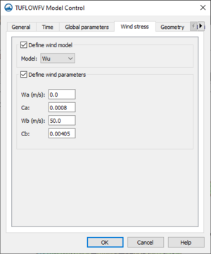
[[File:TUFLOWFV MC Wind.png|thumb|300 px|The ''Wind stress'' tab of the ''TUFLOW FV Model Control'' dialog]] | [[File:TUFLOWFV MC Wind.png|thumb|300 px|The ''Wind stress'' tab of the ''TUFLOW FV Model Control'' dialog]] | ||
The ''Wind stress'' tab of the ''TUFLOW FV Model Control'' dialog contains the following options: | The ''Wind stress'' tab of the ''TUFLOW FV Model Control'' dialog contains the following options: | ||
*Define wind model – Option to define the model used in calculating wind stress for any wind inputs in the simulation. | *''Define wind model'' – Option to define the model used in calculating wind stress for any wind inputs in the simulation. | ||
**Model – Drop-down menu with options for models that can be used to calculate wind stress. | **''Model'' – Drop-down menu with options for models that can be used to calculate wind stress. | ||
***Wu – Sets the wind stress model to the Wu model. Scales wind stress parameterisation based on wind speed. | ***"Wu" – Sets the wind stress model to the Wu model. Scales wind stress parameterisation based on wind speed. | ||
***Constant – Applies wind stress parameterisation using Bulk momentum transfer coefficient as in pre-2019 builds of TUFLOW. | ***"Constant" – Applies wind stress parameterisation using Bulk momentum transfer coefficient as in pre-2019 builds of TUFLOW. | ||
***Kondo – Applies a scaling factor ((for the wind stress parameters??)) using a single term. | ***"Kondo" – Applies a scaling factor ((for the wind stress parameters??)) using a single term. | ||
*Define wind parameters – ((Sets the | *''Define wind parameters'' – ((Sets the wind drag coefficients that the selected model will use to scale the wind stress parameterisation??)) Varies according to the wind model selected. | ||
**Wa – ((??Wind speed in | **''Wa'' – ((??Wind speed in meters per second)) | ||
**Ca – | **''Ca'' – | ||
**Wb – | **''Wb'' – | ||
**Cb – | **''Cb'' – | ||
**Bulk momentum transfer coefficient – | **''Bulk momentum transfer coefficient'' – Sets the coefficient for the Constant wind stress model. | ||
**Scale factor – Sets the scaling factor for the Kondo wind stress model. | **''Scale factor'' – Sets the scaling factor for the Kondo wind stress model. | ||
{{-}} | {{-}} | ||
| Line 154: | Line 156: | ||
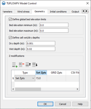
[[File:TUFLOWFV MC Geometry.png|thumb|300 px|The ''Geometry'' tab of the ''TUFLOW FV Model Control'' dialog]] | [[File:TUFLOWFV MC Geometry.png|thumb|300 px|The ''Geometry'' tab of the ''TUFLOW FV Model Control'' dialog]] | ||
The ''Geometry'' tab of the ''TUFLOW FV Model Control'' dialog contains the following options: | The ''Geometry'' tab of the ''TUFLOW FV Model Control'' dialog contains the following options: | ||
*Define global bed elevation limits – Option to apply bed elevation limits | *''Define global bed elevation limits'' – Option to apply bed elevation limits to the entire model. Bed elevations in the model that are outside the set limits will be set to the minimum or the maximum. (Does this change if certain materials are defined contrary to it??)) | ||
**Bed elevation minimum – Defines minimum bed elevation. ((Bed Elevations??Maybe just elevations)) in the model below this value will be set to this value. | **''Bed elevation minimum'' – Defines minimum bed elevation. ((Bed Elevations??Maybe just elevations)) in the model below this value will be set to this value. | ||
**Bed elevation maximum – Defines maximum bed elevations. ((Bed Elevations??Maybe just elevations)) in the model above this value will be set to this value. | **''Bed elevation maximum'' – Defines maximum bed elevations. ((Bed Elevations??Maybe just elevations)) in the model above this value will be set to this value. | ||
*Define cell wet/dry depths – Sets the depth limits that define certain attributes of cells in the model. | *''Define cell wet/dry depths'' – Sets the depth limits that define certain attributes of cells in the model. | ||
**Dry depth – Sets a minimum depth value below which the simulation drops a cell from | **''Dry depth'' – Sets a minimum depth value below which the simulation drops a cell from calculations. | ||
**Wet depth – Sets a minimum depth value below which the simulation sets a cell's momentum to zero | **''Wet depth'' – Sets a minimum depth value below which the simulation sets a cell's momentum to zero. | ||
*Z modifications – | *''Z modifications'' – Options for adjusting and applying elevation data | ||
** | **[[File:Row-add.svg|pi|16 px]] '''Add Row''' – Adds a row of elevation data to the ''Z modifications'' table. | ||
** | **[[File:Row-delete.svg|pi|16 px]] '''Delete Row''' – Deletes the active row of elevation data from the ''Z modifications'' table. | ||
** | **[[File:Row-up.svg|pi|16 px]]'''Move up''' – Moves the selected row of elevation data to be above the row immediately above it. | ||
** | **[[File:Row-down.svg|pi|16 px]] '''Move down''' – Moves the selected row of elevation data to be below the row immediately below it. | ||
**Type – Option to select which type of elevation input is desired on this row of data. | **''Type'' – Option to select which type of elevation input is desired on this row of data. The other columns in the table become active or inactive based on the type selected here. | ||
**''Set Zpts'' – Sets elevation values for the center of all cells in the model domain to the given value. | |||
**GRID Zpts – Interpolates a grid file to set mesh cell center | **''GRID Zpts'' – Interpolates a grid file to set elevations for the mesh cell center. Select '''(none selected)''' to open a dialog box and select the desired grid file. Either .asc or .flt. can be used for this feature. | ||
**CSV File – Option to update cell elevations using a .csv file. The .csv file can identify cells using x,y coordinates or cell IDs. | **''CSV File'' – Option to update cell elevations using a .csv file. The .csv file can identify cells using x,y coordinates or cell IDs. | ||
**CSV Type – Select which type of data the .csv file will contain. | **''CSV Type'' – Select which type of data the .csv file will contain. | ||
***Cell ID – Sets the program to read the .csv file data for cell IDs matched with elevation data. | ***"Cell ID" – Sets the program to read the .csv file data for cell IDs matched with elevation data. | ||
***Coordinate – Sets the program to read the .csv file data for x,y coordinates matched with elevation data. | ***"Coordinate" – Sets the program to read the .csv file data for x,y coordinates matched with elevation data. | ||
**ZLine Shapes – Sets breakline features and polygon features according to an already imported .shp or | **''ZLine Shapes'' – Sets breakline features and polygon features according to an already imported .shp or .mif/.mid file. Select '''(none selected)''' to open a dialog and select the desired file (all RC sees is coverages here, but maybe they are the only things available. They don't seem like any of the described file types??). | ||
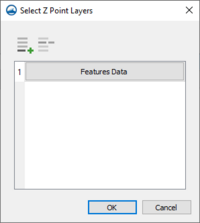
**ZPoint Shapes – Sets elevation points according to an already imported .shp or | **''ZPoint Shapes'' – Sets elevation points according to an already imported .shp or .mif/.mid file. Using this feature, multiple layers of elevation information can be used. This allows for dividing the layers for better data management. Select '''(none selected)''' to open the ''Select Z Point Layers'' dialog. | ||
=====Select Z Point Layers===== | |||
[[File:TUFLOWFV MC Geometry Select Zpt Layers.png|thumb|200 px|The ''Select Z Point Layers'' dialog which opens when '''Select Z Point Layers...''' is clicked in the ''Geometry'' tab.]] | |||
**[[File:Row-add.svg|pi|16 px]] '''Add Row''' – Opens a dialog for selecting a file (??to define the Z point layer). Adds that layer to a new table row. | |||
**[[File:Row-delete.svg|pi|16 px]] '''Delete Row''' – Deletes the active row of data. | |||
{{-}} | {{-}} | ||
| Line 179: | Line 185: | ||
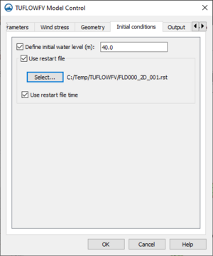
[[File:TUFLOWFV MC Initial.png|thumb|300 px|The ''Initial conditions'' tab of the ''TUFLOW FV Model Control'' dialog]] | [[File:TUFLOWFV MC Initial.png|thumb|300 px|The ''Initial conditions'' tab of the ''TUFLOW FV Model Control'' dialog]] | ||
The ''Initial conditions'' tab of the ''TUFLOW FV Model Control'' dialog contains the following options: | The ''Initial conditions'' tab of the ''TUFLOW FV Model Control'' dialog contains the following options: | ||
*''Define initial water level'' – Option set water level to a constant value for the entire simulation. It's best for the water level boundary conditions for the initial | *''Define initial water level'' – Option set water level to a constant value for the entire simulation. It's best for the water level boundary conditions for the initial time steps to be as close as possible to this setting. | ||
*''Use restart file'' – Option to use a restart file to define | *''Use restart file'' – Option to use a restart file to define the initial conditions for the current run. The restart file must come from a model that uses the same mesh, bathymetry, vertical layering, and number of conserved variables as the model for the current simulation. | ||
**'''Select...''' – Opens dialog box for selecting restart file to be used. | **'''Select...''' – Opens dialog box for selecting restart file to be used. | ||
**''Use restart file time'' – Option to use the time stamp on the restart file as the starting time of the current run. On by default. | **''Use restart file time'' – Option to use the time stamp on the restart file as the starting time of the current run. On by default. | ||
| Line 186: | Line 192: | ||
====Output==== | ====Output==== | ||
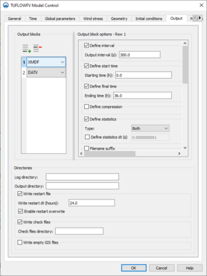
[[File:TUFLOWFV MC Output.png|thumb|300px|The ''Output'' tab of the ''TUFLOWFV Model Control'' dialog.]] | |||
The ''Output'' tab of the ''TUFLOW FV Model Control'' dialog contains the following options: | The ''Output'' tab of the ''TUFLOW FV Model Control'' dialog contains the following options: | ||
*''Output blocks'' – | *''Output blocks'' – Output blocks set output file types as well as certain output file properties. They also allow for selecting desired datasets to be included in the output file and the time steps at which to output the information. | ||
**[[File:Row-add.svg|pi|16 px]] '''Add Row''' – Adds a output block to the ''Output blocks'' table. | **[[File:Row-add.svg|pi|16 px]] '''Add Row''' – Adds a output block to the ''Output blocks'' table. | ||
**[[File:Row-delete.svg|pi|16 px]] '''Delete Row''' – Deletes the selected output block from the ''Output blocks'' table. | **[[File:Row-delete.svg|pi|16 px]] '''Delete Row''' – Deletes the selected output block from the ''Output blocks'' table. | ||
**"DATV" – | **"DATV" – SMS will give mapped output in DATV format with user specified datasets and parameters. Often used for data visualization in SMS. | ||
**"XMDF" – | **"XMDF" – SMS will give mapped output in XMDF format with user specified datasets and parameters. Often used for data visualization in SMS. | ||
**"NetCDF" – | **"NetCDF" – SMS will give mapped output in NetCDF (network Common Data Form) format with user specified datasets and parameters. Includes mapped output information at the desired time intervals as well as information about model geometry. | ||
**"Flux" – Outputs a CSV file | **"Flux" – Outputs a CSV file that will give the values of fluid flow and, if applicable, the movement of other quantities that cross model boundaries or other specified nodestrings. | ||
**"Mass" – Outputs a CSV file that can be used to check certain simulated quantities, mainly the volume of fluid within the model domain. | **"Mass" – Outputs a CSV file that can be used to check certain simulated quantities, mainly the volume of fluid within the model domain. | ||
**"Points" – Outputs a CSV file containing model parameter time-series. This includes coordinates and associated data for the points of interest ((as defined in a coverage dedicated to this task.??)) | **"Points" – Outputs a CSV file containing model parameter time-series. This includes coordinates and associated data for the points of interest ((as defined in a coverage dedicated to this task.??)) | ||
**"Transport" – Outputs a NetCDF file | **"Transport" – Outputs a NetCDF file that can be used to improve the runtime of subsequent advection-diffusion, sediment, or particle tracking simulations. It stores conserved variables on the TUFLOW FV mesh for use in future simulations. | ||
*''Output block options - Row (value of active row)'' – Gives options to define attributes and datasets for a selected output block. Many options are only available when certain output blocks are selected. (See table below) | *''Output block options - Row (value of active row)'' – Gives options to define attributes and datasets for a selected output block. Many options are only available when certain output blocks are selected. (See table below) | ||
**''Output points feature coverage'' – Only available when a "Points" output block is active. Click '''Select...''' to set the coverage that will define the coordinates of the desired output points | **''Output points feature coverage'' – Only available when a "Points" output block is active. Click '''Select...''' to set the coverage that will define the coordinates of the desired output points | ||
**''Define Interval'' – Option to set the interval for the specified output in seconds. If not specified, the program will produce the specified output at every | **''Define Interval'' – Option to set the interval for the specified output in seconds. If not specified, the program will produce the specified output at every time step, sometimes resulting in output files that are too large. | ||
**''Define start time'' – Sets output request start time. When not specified, the output start time will be the simulation start time. Time format will be the same as format selected under the ''Time'' tab. | **''Define start time'' – Sets output request start time. When not specified, the output start time will be the simulation start time. Time format will be the same as format selected under the ''Time'' tab. | ||
**''Define final time'' – Sets output request final time. When not specified, the output final time will be the simulation end time. Time format will be the same as format selected under the ''Time'' tab. | **''Define final time'' – Sets output request final time. When not specified, the output final time will be the simulation end time. Time format will be the same as format selected under the ''Time'' tab. | ||
**''Define compression'' – | **''Define compression'' – Option to compress output file. | ||
***''Compression on'' – If turned on, output file will be compressed. On by default. | ***''Compression on'' – If turned on, output file will be compressed. On by default. | ||
**''Define Statistics'' – Option to track minimum and/or maximum values of selected datasets | **''Define Statistics'' – Option to track minimum and/or maximum values of selected datasets. | ||
***''Type'' – Select the values to track from the drop-down menu. | ***''Type'' – Select the values to track from the drop-down menu. | ||
****"Both" – Both maximum and minimum values for selected datasets will be tracked. | ****"Both" – Both maximum and minimum values for selected datasets will be tracked. | ||
| Line 211: | Line 218: | ||
****"Maximums" – Only maximum values for selected datasets will be tracked. | ****"Maximums" – Only maximum values for selected datasets will be tracked. | ||
***''Define statistics dt'' – Option to define independent output interval for tracking of minimum and maximum values. If not defined, defaults to 0 and uses the model interval. | ***''Define statistics dt'' – Option to define independent output interval for tracking of minimum and maximum values. If not defined, defaults to 0 and uses the model interval. | ||
**''Filename suffix'' – | **''Filename suffix'' – Option to specify a desired suffix for output file. | ||
**''Datasets'' – | **''Datasets'' – Specify datasets for inclusion in output file. This will only appear when a DATV, XMDF, NetCDF, or points output block is active. For more information, see the table below. | ||
*''Directories'' | *''Directories'' | ||
**''Log directory'' – Option to specify ((directory??)) for simulation log file (.log) output. When not specified, log file will be written to same location as simulation control file. | **''Log directory'' – Option to specify ((directory??)) for simulation log file (.log) output. When not specified, log file will be written to same location as simulation control file. | ||
**''Output directory'' – Option to specify location in which simulation output files will be written. When not specified, output files will be written to same location as simulation control file. | **''Output directory'' – Option to specify location in which simulation output files will be written. When not specified, output files will be written to same location as simulation control file. | ||
**''Write restart file'' – | **''Write restart file'' – TUFLOW FV writes the values of the selected datasets in each cell at desired regular time steps. Specify these time steps in ''Write restart dt''. | ||
***''Write restart dt'' – Specify the desired interval of | ***''Write restart dt'' – Specify the desired interval of time steps at which TUFLOW FV will write the restart file. | ||
***''Enable restart overwrite'' – Option to overwrite the restart file being used at the time interval specified in ''Write restart dt''. On by default. | ***''Enable restart overwrite'' – Option to overwrite the restart file being used at the time interval specified in ''Write restart dt''. On by default. | ||
**''Write check files'' – Option to create a number of check files that can be used to verify model inputs. | **''Write check files'' – Option to create a number of check files that can be used to verify model inputs. | ||
| Line 347: | Line 354: | ||
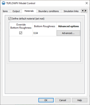
[[File:TUFLOWFV MC Material.png|thumb|300 px|The ''Materials'' tab of the ''TUFLOW FV Model Control'' dialog]] | [[File:TUFLOWFV MC Material.png|thumb|300 px|The ''Materials'' tab of the ''TUFLOW FV Model Control'' dialog]] | ||
The ''Materials'' tab of the ''TUFLOW FV Model Control'' dialog contains the following options: | The ''Materials'' tab of the ''TUFLOW FV Model Control'' dialog contains the following options: | ||
*''Define default material (set mat)'' – ((?? | *''Define default material (set mat)'' – ((??Sets the material settings for every cell in the model domain. This material and its attributes will be the assumed material for each cell ((unless a material block defines them otherwise??)) | ||
**''Override Bottom Roughness'' – | **''Override Bottom Roughness'' – Select to allow for editing bottom roughness of this material. | ||
**''Bottom Roughness'' – | **''Bottom Roughness'' – Sets the default bottom roughness for the entire model. Will be factored in according to the bottom drag model selected on the ''Global parameters'' tab. | ||
**''Advanced Options'' – Select '''Advanced...''' to open the ''Materials (advanced) - Default material (set mat)'' dialog. | **''Advanced Options'' – Select '''Advanced...''' to open the ''Materials (advanced) - Default material (set mat)'' dialog. | ||
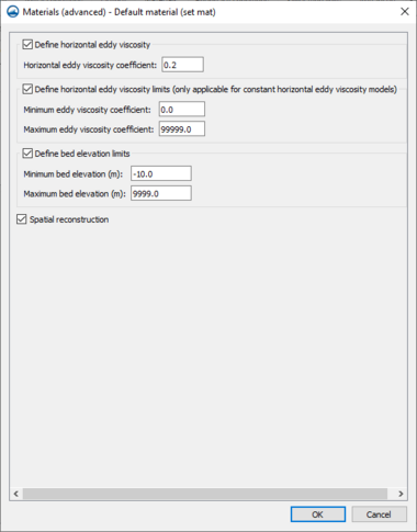
=====Materials (advanced) - Default material (set mat)===== | =====Materials (advanced) - Default material (set mat)===== | ||
*''Define horizontal eddy viscosity'' – | *''Define horizontal eddy viscosity'' – Option to adjust the horizontal eddy viscosity settings for this material. The input asked for here varies depending on the horizontal mixing model selected on the ''Global Parameters'' tab. | ||
**''Horizontal eddy viscosity'' – | **''Horizontal eddy viscosity'' – Sets the horizontal eddy viscosity for this material. Only available when ''Horizontal mixing model'' under ''Global Parameters'' is set to "None" or "Constant". | ||
*''Define bed elevations limits'' – | **''Horizontal eddy viscosity coefficient'' – Sets the coefficient for either the "Wu" or "Smagorinsky" mixing models, depending on the model selected on the ''Global Parameters'' tab. Only available when ''Horizontal mixing model'' under ''Global Parameters'' is set to ''Smagorinsky'' or ''Wu''. | ||
**''Minimum bed elevation'' – | *''Define bed elevations limits'' – Option to set limits for the bed elevation of cells defined by this material. | ||
**''Maximum bed elevation'' – | **''Minimum bed elevation'' – Sets minimum bed elevation. | ||
*''Spatial reconstruction'' – | **''Maximum bed elevation'' – Sets maximum bed elevation. | ||
*''Spatial reconstruction'' – Option to limit spatial reconstruction (??for cells that are defined by the default material). This reverts the calculations for this area to first-order calculations in a model that is second-order. This has no effect if the model is already first order as defined in the ''General'' tab under ''Define spatial order''. | |||
[[File:TUFLOWFV MC Materials Advanced DM Set Mat.png|left|380px|The ''Materials (advanced) - Default material (set mat)'' dialog which opens when '''Advanced...''' is selected on the ''Materials'' tab.]] | |||
{{-}} | {{-}} | ||
====Boundary Conditions==== | ====Boundary Conditions==== | ||
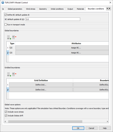
[[File:TUFLOWFV MC Boundary Conditions.png|thumb|450px|The ''Boundary Conditions'' tab on the ''TUFLOWFV Model Control'' dialog.]] | |||
The ''Boundary conditions'' tab of the ''TUFLOW FV Model Control'' dialog contains the following options: | The ''Boundary conditions'' tab of the ''TUFLOW FV Model Control'' dialog contains the following options: | ||
*''Define BC default update dt'' – Option to set the | *''Define BC default update dt'' – Option to set the time step for all boundary conditions to update. If unspecified, TUFLOW FV will interpolate values to each time step. If specified, TUFLOW FV will keep all values after one update but before the next update at a constant value. | ||
**''BC default update dt'' – ((sets the time value of the | **''BC default update dt'' – ((sets the time value of the time steps that TUFLOW FV will interpolate to??)) | ||
*''Run in transport mode'' – Option to run a simulation that includes a transport boundary condition. | *''Run in transport mode'' – Option to run a simulation that includes a transport boundary condition. This option can be useful for later models that use many of the same conditions but require different inputs. | ||
**''Transport BC file'' – Click '''Select...''' to set which transport file will be used in this simulation. | **''Transport BC file'' – Click '''Select...''' to set which transport file will be used in this simulation. | ||
*''Global boundaries'' – ((Boundary condition blocks that can be used to apply conditions to every cell in the model domain. For example, it can be used to account for inflow from rain or evaporation. | *''Global boundaries'' – ((Boundary condition blocks that can be used to apply conditions to every cell in the model domain. For example, it can be used to account for inflow from rain or evaporation. | ||
**[[File:Row-add.svg|pi|16 px]]'''Add row''' – Adds a boundary condition block that specifies conditions over the entire model domain. | **[[File:Row-add.svg|pi|16 px]]'''Add row''' – Adds a boundary condition block that specifies conditions over the entire model domain. | ||
**[[File:Row-delete.svg|pi|16 px]]'''Delete row''' – Deletes the active | **[[File:Row-delete.svg|pi|16 px]]'''Delete row''' – Deletes the active global boundary condition block. | ||
**''Type'' – Shows the type of boundary condition assigned to this boundary condition block. | **''Type'' – Shows the type of boundary condition assigned to this boundary condition block. | ||
**''Attributes'' | **''Attributes'' | ||
***'''Assign BC''' – Opens the ''Assign Global Boundary Condition'' dialog. | ***'''Assign BC''' – Opens the ''Assign Global Boundary Condition'' dialog. | ||
*''Gridded boundaries'' – So are we applying multiple boundary conditions to the one grid? That's what's happening here?? | *''Gridded boundaries'' – So are we applying multiple boundary conditions to the one grid? That's what's happening here?? | ||
** [[File:Row-add.svg|pi|16 px]]'''Add row''' – | ** [[File:Row-add.svg|pi|16 px]]'''Add row''' – Adds a Gridded BC row to the ''Gridded boundaries'' table. Opens the ''Define BC Grid'' dialog. | ||
** [[File:Row-delete.svg|pi|16 px]]'''Delete row''' – Deletes a Gridded BC row from the ''Gridded boundaries'' table. | ** [[File:Row-delete.svg|pi|16 px]]'''Delete row''' – Deletes a Gridded BC row from the ''Gridded boundaries'' table. | ||
**''Grid Definition'' | **''Grid Definition'' | ||
***'''Define Grid...''' – Opens ''Define BC Grid'' dialog for selecting the grid and associated settings for selected grid definition block. | ***'''Define Grid...''' – Opens ''Define BC Grid'' dialog for selecting the grid and associated settings for selected grid definition block. | ||
**''Boundaries'' | **''Boundaries'' | ||
***'''Define BCs...''' – Opens ''Add Gridded BCs'' dialog. | ***'''Define BCs...''' – Opens ''Add Gridded BCs'' dialog. | ||
*''Global wave options'' | *''Global wave options'' &ndash: Options for use if a linked Boundary Conditions coverage with a wave boundary type and/or a gridded wave boundary defined. | ||
**''Include wave stress'' – | **''Include wave stress'' – | ||
**''Include Stokes drift'' – Option to include Stokes drift in calculations ((Interpolates mass transport for cells between the deepwater and surfzone depth??)) | **''Include Stokes drift'' – Option to include Stokes drift in calculations ((Interpolates mass transport for cells between the deepwater and surfzone depth??)) | ||
======Assign Global Boundary Condition====== | ======Assign Global Boundary Condition====== | ||
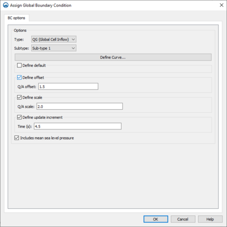
[[File:TUFLOWFV MC BC Assign Global BC.png|thumb|450px|The ''Assign Global Boundary Condition'' dialog which opens when '''Assign BC''' is selected on the ''Boundary conditions'' tab.]] | |||
*''Options'' – | *''Options'' – | ||
**''Type'' – Sets which type of boundary condition to set globally for the model. ( | **''Type'' – Sets which type of boundary condition to set globally for the model. The one option is "QG (Global Cell Inflow)". | ||
***"QG (Global Cell Inflow)" – Sets boundary condition as flow into every cell in model domain. Useful to account for effects of rain or evaporation. | ***"QG (Global Cell Inflow)" – Sets boundary condition as flow into every cell in model domain. Useful to account for effects of rain or evaporation. | ||
**''Subtype'' – Option to adjust how a boundary type functions numerically in the model | **''Subtype'' – Option to adjust how a boundary type functions numerically in the model. | ||
***"Sub-type 1" – | ***"Sub-type 1" – The interior model concentration will be used to determine the scalar flux. | ||
***"Sub-type 2" – | ***"Sub-type 2" – The value specified in the BC file will determine the scalar flux. | ||
**'''Define Curve...''' – Opens "BC Curve Editor" dialog. | **'''Define Curve...''' – Opens "BC Curve Editor" dialog. | ||
**''Define default'' – | **''Define default'' – Defines default value for a given variable when TUFLOW FV gets a null-value from a boundary condition input. | ||
***''Q/A default'' – | ***''Q/A default'' – | ||
**''Define offset'' – | **''Define offset'' – Sets the offset that TUFLOW FV will add to each variable of raw boundary condition data as it is read into TUFLOW FV. Offset will be added to each variable after it is multiplied by the set scale | ||
***''Q/A offset'' – | ***''Q/A offset'' – | ||
**''Define scale'' – | **''Define scale'' – Sets the scale by which TUFLOW FV will multiply each variable of raw boundary condition data as it is read into TUFLOW FV. The data will be multiplied by the scale before the offset value for each variable is added. | ||
***''Q/A scale'' – | ***''Q/A scale'' – | ||
**''Define update increment'' – | **''Define update increment'' – Sets update intervals of time steps for boundary conditions. When not set, TUFLOW FV will update the boundary condition at every simulation time step. | ||
***''Time'' – | ***''Time'' – The value of the update intervals of time steps. | ||
**''Includes mean sea level pressure'' – | **''Includes mean sea level pressure'' – Option to specify if an inverse barometer offset is already included in a water level boundary condition. By default, it is on to indicate there is an inverse barometer offset included. If turned off, the difference between the local MSLP and the reference MSLP will be applied at the boundary. | ||
======BC Curve Editor====== | ======BC Curve Editor====== | ||
<!--This is the only dialog that RC didn't upload an image for--> | |||
*''Define reference time'' – | *''Define reference time'' – | ||
**''Use ISODate'' – | **''Use ISODate'' – | ||
| Line 414: | Line 426: | ||
=====Define BC Grid===== | =====Define BC Grid===== | ||
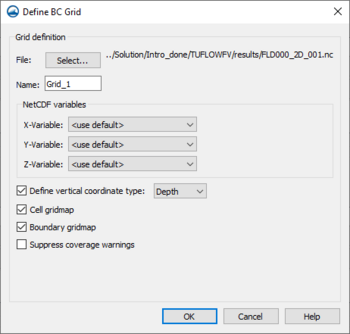
[[File:TUFLOWFV MC BC Define BC Grid.png|thumb|350px|The ''Define BC Grid'' dialog, which opens when '''Define Grid''' is selected in ''Boundary conditions'' tab.]] | |||
*''Grid Definition'' – Space for defining the location, filename, and settings for a NetCDF file that will be used to map input files to the model mesh. | *''Grid Definition'' – Space for defining the location, filename, and settings for a NetCDF file that will be used to map input files to the model mesh. | ||
**''File'' – Click '''Select...''' to set the NetCDF file that contains the coordinates that define a grid. The gridded boundary conditions will be applied to this grid. | **''File'' – Click '''Select...''' to set the NetCDF file that contains the coordinates that define a grid. The gridded boundary conditions will be applied to this grid. | ||
**''Name'' – Name applied to the grid | **''Name'' – Name applied to the grid. Name might be used later to refer to this grid by other boundary conditions in this model. | ||
**''NetCDF variables'' – Sets the variables from the NetCDF file that the program should use to create the grid map. | **''NetCDF variables'' – Sets the variables from the NetCDF file that the program should use to create the grid map. | ||
***''X-Variable'' – | ***''X-Variable'' – | ||
***''Y-Variable'' – | ***''Y-Variable'' – | ||
***''Z-Variable'' – | ***''Z-Variable'' – | ||
**''Define vertical coordinate type'' – Option to specify the vertical coordinate convention. The different convention names correspond to distinct kinds of depth averaging. | **''Define vertical coordinate type'' – Option to specify the vertical coordinate convention. The different convention names correspond to distinct kinds of depth averaging. | ||
***"Elevation" – [https://fvwiki.tuflow.com/index.php?title=Depth_Averaging_Results]. Here is the information. Not sure how to interpret it yet. | ***"Elevation" – [https://fvwiki.tuflow.com/index.php?title=Depth_Averaging_Results]. Here is the information. Not sure how to interpret it yet. | ||
***"Depth" – | ***"Depth" – | ||
***"Sigma" – | ***"Sigma" – | ||
***"Height" – | ***"Height" – | ||
**''Cell gridmap'' – When turned off | **''Cell gridmap'' – When turned off, (I have found info for this, but do not yet know how to rephrase it.) | ||
**''Boundary gridmap'' – If on, calculates | **''Boundary gridmap'' – If on, calculates (I have found info for this, but do not yet know how to rephrase it.) | ||
**''Suppress coverage warnings'' – Will suppress warnings that indicate the grid does not cover the entire domain. | **''Suppress coverage warnings'' – Will suppress warnings that indicate the grid does not cover the entire domain. | ||
=====Add Gridded BCs===== | =====Add Gridded BCs===== | ||
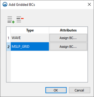
[[File:TUFLOWFV MC BC Add Gridded BC.png|thumb|300px|The ''Add Gridded BCs'' dialog which opens when '''Define BCs...''' is selected on the ''Boundary Conditions'' tab.]] | |||
This dialog allows for assigning ((??multiple boundary)) conditions to the one grid in the selected row??. | This dialog allows for assigning ((??multiple boundary)) conditions to the one grid in the selected row??. | ||
* [[File:Row-add.svg|pi|16 px]]'''Add row''' – Adds a gridded boundary condition block ((to the grid associated with the active grid block??)) | |||
* [[File:Row-delete.svg|pi|16 px]]'''Delete row''' – Deletes the selected gridded boundary condition block. | |||
*''Type'' – Shows the type of boundary condition grid assigned to this boundary condition block. | |||
*''Attributes'' – | |||
**'''Assign BC...''' – Opens ''Assign Gridded Boundary Condition'' dialog. | |||
======Assign Gridded Boundary Condition====== | ======Assign Gridded Boundary Condition====== | ||
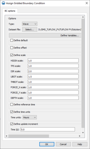
[[File:TUFLOWFV MC BC Assign Gridded BC.png|thumb|300px|''Assign Gridded Boundary Condition'' dialog which opens when '''Assign BC...''' is selected in the ''Add Gridded BCs'' dialog.]] | |||
*''Options'' – TUFLOW Manual 15.4.4 BC Scale and BC Offset | *''Options'' – TUFLOW Manual 15.4.4 BC Scale and BC Offset | ||
**''Type'' – | **''Type'' – Sets type of boundary condition to be used. | ||
***"MSLP_Grid" – | ***"MSLP_Grid" – Sets boundary condition type to mean sea level pressure field (grid??). | ||
***"W10_Grid" – | ***"W10_Grid" – Sets boundary condition type to wind velocity at 10m (grid??)) . | ||
***"Wave" – | ***"Wave" – | ||
**''Dataset file'' – | **''Dataset file'' – Opens dialog to select NetCDF file to define the data for the boundary condition. | ||
**'''Define Variables''' – Opens ''Select NetCDF Gridded BC Variable Names'' dialog. | **'''Define Variables''' – Opens ''Select NetCDF Gridded BC Variable Names'' dialog. | ||
**''Define default'' | **For ''Define default'', ''Define offset'', ''Define scale'', ''Define reference time'', ''Define time units'', and ''Define update increment'', see table below. | ||
{| class="wikitable" | {| class="wikitable" | ||
!Grid Type | !Grid Type | ||
!Option or Variable | !Option or Variable | ||
!Definition | ! scope="col" style="width: 550px;" | Definition | ||
|- | |- | ||
|colspan="15"| | |colspan="15"| | ||
| Line 472: | Line 473: | ||
|- | |- | ||
!rowspan="6" | All Grids | !rowspan="6" | All Grids | ||
|Define default | |''Define default'' | ||
| | |Defines default value for a given variable when a boundary condition input gives TUFLOW FV a null-value. | ||
|- | |- | ||
|Define offset | |''Define offset'' | ||
| | |Sets the offset that TUFLOW FV will add to each variable of raw boundary condition data as it is read into TUFLOW FV. Offset will be added to each variable after it is multiplied by the set scale. | ||
|- | |- | ||
|Define scale | |''Define scale'' | ||
| | |Sets the scale by which TUFLOW FV will multiply each variable of raw boundary condition data as it is read into TUFLOW FV. The data will be multiplied by the scale before the offset value for each variable is added. | ||
|- | |- | ||
|Define reference time | |''Define reference time'' | ||
| | |Sets reference time for the boundary condition. When not set, the reference time will be the same as the simulation time. Option set reference time in hours, which is the default. Turn on ''Use ISODate'' to use that format if desired. | ||
|- | |- | ||
|Define time units | |''Define time units'' | ||
| | |Sets time units to be used for the boundary condition. The options are: | ||
*"Days" | |||
*"Hours" | |||
*"Minutes" | |||
*"Seconds" | |||
*"Isotime" | |||
|- | |- | ||
|Define update increment | |''Define update increment'' | ||
| | |Sets update intervals of time steps for boundary conditions. When not set, TUFLOW FV will update the boundary condition at every simulation time step. | ||
|- | |- | ||
! | !rowspan="1" | MSLP_Grid | ||
|''MSLP'' | |||
|Mean sea level pressure | |||
|- | |||
!rowspan="2" | W10_Grid | |||
|''W10_X'' | |||
|"10 m wind speed vector" | |||
|- | |||
|''W10_Y'' | |||
|"10 m wind speed vector" | |||
|- | |||
!rowspan="8" | Wave | |||
|''HSIGN'' | |||
|Significant wave height?? (In TUFLOW FV documentation, it's usually called HSIG except for in Table 15-3.) | |||
|- | |||
|''TPS'' | |||
|Smoothed peak wave period | |||
|- | |||
|''DIR'' | |||
|Mean wave direction. This is direction to which waves are heading when the | |||
|- | |||
|''UBOT'' | |||
|The rms-value (root mean square value?) of the maxima of the orbital velocity near the bottom. If it is left undefined, TUFLOW FV will calculate it using linear wave theory. | |||
|- | |||
|''TMBOT'' | |||
|The bottom wave period | |||
|- | |||
|''FORCE_X'' | |||
|X wave induced force vector component (In TUFLOW FV documentation, it's usually called WFORCE_X except for in Table 15-3 | |||
|- | |||
|''FORCE_Y'' | |||
|Y wave induced force vector component (In TUFLOW FV documentation, it's usually called HSIG except for in Table 15-3.) | |||
|- | |- | ||
|''DEPTH'' | |||
| | |Wave model water depth | ||
|} | |} | ||
======Select NetCDF Gridded BC Variable Names====== | ======Select NetCDF Gridded BC Variable Names====== | ||
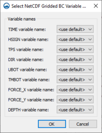
*''Variable names'' – The variables that appear | [[File:TUFLOWFV MC BC Select NetCDF Gridded Variable Names.png|thumb|200px|The ''Select NetCDF Gridded BC Variable Names'' dialog which opens when '''Define Variables...''' is selected under the ''Assign Gridded Boundary Condition'' dialog. This dialog is for a "Waves" boundary condition type as selected on the ''Assign Gridded Boundary Condition'' dialog.]] | ||
**''TIME variable name'' – | *''Variable names'' – The variables that appear (other than TIME, which appears no matter which grid type is selected) will be exactly the same as the variables that appear in the ''Assign Gridded Boundary Condition'' dialog under ''Define default'', ''Define offset'', and ''Define scale''. It varies depending on the grid type selected. | ||
**''TIME variable name'' – (??Advanced option to select a ??header in the selected file for the TIME variable. Does this vary depending on what file you have selected? <!--Jeff, there's not much information, but it's on page 335 in Appendix F of TUFLOW FV manual--> | |||
** | **Grid Specific variables | ||
*** | ***MSLP_GRID variables: | ||
*** | ****''MSLP variable name'' – Advanced option to select a header in the selected file for the MSLP variable. | ||
*** | ***W10_GRID variables: | ||
*** | ****''W10_X variable name'' – Advanced option to select a header in the selected file for the W10_X variable. | ||
*** | ****''W10_Y variable name'' – Advanced option to select a header in the selected file for the W10_Y variable. | ||
*** | ***Wave variables: | ||
*** | ****''HSIGN variable name'' – Advanced option to select a header in the selected file for the HSIGN variable. | ||
*** | ****''TPS variable name'' – Advanced option to select a header in the selected file for the TPS variable. | ||
*** | ****''DIR variable name'' – Advanced option to select a header in the selected file for the DIR variable. | ||
* | ****''UBOT variable name'' – Advanced option to select a header in the selected file for the UBOT variable. | ||
*** | ****''TMBOT variable name'' – Advanced option to select a header in the selected file for the TMBOT variable. | ||
* | ****''FORCE_X variable name'' – Advanced option to select a header in the selected file for the FORCE_X variable. | ||
*** | ****''FORCE_Y variable name'' – Advanced option to select a header in the selected file for the FORCE_Y variable. | ||
* | ****''DEPTH variable name'' – Advanced option to select a header in the selected file for the DEPTH variable. | ||
*** | |||
* | |||
*** | |||
* | |||
** | |||
**'' | |||
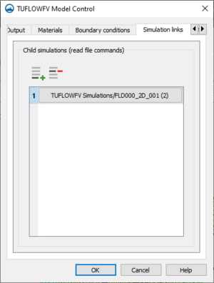
====Simulation links==== | ====Simulation links==== | ||
Latest revision as of 16:13, 16 August 2022
| TUFLOW FV | |
|---|---|
| Model Info | |
| Model type | Two-dimensional (2D) flexible mesh finite volume flood, tide and water quality simulation software. |
| Developer | WBM BMT WBM (Australia) |
| Web site | www.tuflow.com |
| Tutorials | SMS Learning Center |
TUFLOW FV (which stands for Two-dimensional Unsteady FLOW Finite Volume) is a flexible mesh finite volume numerical model that simulates hydrodynamic, sediment transport and water quality processes in oceans, coastal waters, estuaries and rivers. The model may be used for coastal and nearshore environments including beaches and coastlines as well as offshore environments such as estuaries, river entrances and deltas, and floodplains. Uses include modeling river flood flow, tsunami inundation (the finite-volume scheme is well suited for a tsunami's mixed sub/super-critical flow regimes), beach erosion, ocean pollution, and estuary flow.
Unlike the fixed square grids of TUFLOW Classic, the flexible triangular or quadrilateral mesh of TUFLOW FV allows users to modify mesh resolution spatially, seamlessly increasing the model resolution in areas of interest. This modelling approach reduces the number of computation cells needed in a model reducing run times. Additionally, TUFLOW FV can be run in parallel on multiple processors, threads, or computers.
The TUFLOW FV model can be added to a paid edition of SMS.
TUFLOW FV ENGINE
The TUFLOW computational engine computes 2D hydraulic solutions. The engine uses a macro style text-file input which allows the user to flexibly and efficiently control model configurations and simulations.
For more information see the TUFLOW FV webpage.
SMS Interface
The TUFLOW FV engine is interfaced in SMS through the dynamic model interface. It makes use of the SMS simulation workflow.
TUFLOW FV Coverages
TUFLOW FV simulations require a boundary condition coverage and a materials coverage.
Boundary Conditions Coverage
The TUFLOW FV boundary conditions coverage allows assigning boundary condition attributes to arcs drawn in the coverage. These attributes will then be assigned, or snapped, to the 2D mesh during the simulation run.
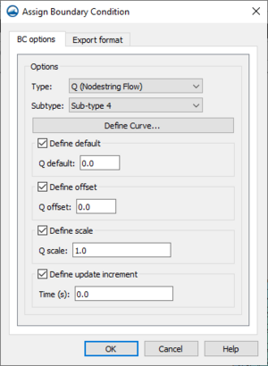
Attributes are assigned to arcs by right-clicking a selected arc and selecting the Assign BC command. This will open the Assign Boundary Condition dialog for TUFLOW FV.
The TUFLOW FV Assign Boundary Condition dialog has the following options:
BC Options – The BC Options tab has options for assigning attributes to the arc.
- Type – The option here determines what type of boundary condition will be assigned to the arc. The following types are available:
- "Monitor" – Sets the arc to be a monitoring line.
- "HQ (Head Discharge)" –
- "Q (Nodestring Flow)"
- "QN (Head Discharge)"
- "WL (Water Level)"
- "WLS (Sloping Water Level"
- "WL_CURT (Water Level Curtain"
- "ZG (Zero Gradient)"
- Subtype
- Define Curve
- Friction slope
- Dataset file
- Define Varaibles
- View Curve
- Define default
- 'Q default
- Define offset
- Q offset
- Define scale
- Q scale
- Define update increment
- Time
- Include mean sea level pressure
Materials
The TUFLOW FV materials coverage allows creating the polygons to hold the material attributes for the simulation run. The assigned material attributes will be mapped to the mesh/grid during the simulation run.
TUFLOW FV Simulation Menu
The TUFLOW FV simulation item in the Project Explorer contains a right-click menu with commands for accessing TUFLOW FV simulation options. The menu has the following commands:
- Simulation Run Queue – Opens the Simulation Run Queue dialog.
- Model Control – Opens the TUFLOWFV Model Control dialog.
- Save Simulation – Saves the simulations and exports the simulations files needed for the simulation run.
- Run Simulation – Runs the simulation using the exported simulation files. will bring up the Simulation Run Queue dialog.
- Save Project, Simulation and Run – Exports the simulation files, saves the project and project files, and runs the simulation. Will bring up the Simulation Run Queue dialog.
- Read Solution – Opens a browser to import the solution files.
- Simulation Properties – Opens the Simulation Propertes dialog where basic information about the simulation can be viewed.
The specific menu commands may be different depending on the selected option in the Preferences dialog.
TUFLOW FV Model Control
The TUFLOW FV Model Control dialog contains options for setting the parameters that will be used during the simulation run. The dialog is accessed by right-clicking on the simulation in the Project Explorer and selecting the Model Control command. The dialog contains multiple options organized on multiple tables. The options are as follows:
General
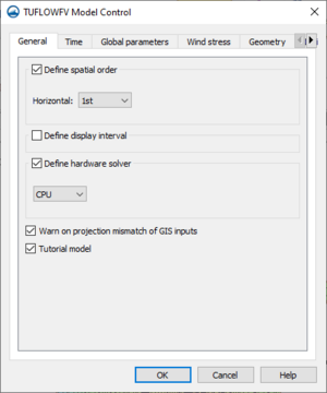
The General tab of the TUFLOW FV Model Control dialog contains the following options:
- Define spatial order – Option to define horizontal spatial scheme.
- Horizontal – Select "1st" order scheme or "2nd" order scheme.
- "1st" – Sets the simulation to use a 1st order scheme. This can be used when there is not a significant difference between the results for 1st and 2nd order schemes. It's also generally used for the beginning stages of most model development.
- "2nd" – Sets the simulation to use a 2nd order scheme. This is used when a significant difference is noticed between 1st and 2nd order schemes. It's usually tested in more advanced stages of model development. Fast-changing flow conditions or high gradients in conserved variables might warrant or necessitate use of this spatial scheme.
- Horizontal – Select "1st" order scheme or "2nd" order scheme.
- Define display interval – Option to set the interval in seconds at which time step information will be displayed to the (log and terminal window??).
- Display interval – Sets the interval in seconds for the display of time step information.
- Define hardware solver – Option to enable computing through the CPU or the GPU. Can produce slight differences in results.
- "CPU" – Calculations will use the "Central Processing Unit".
- "GPU" – Calculations will use the "Graphical Processing Unit". Using GPU with TUFLOW
- Device ID – Option to select which GPU device is used for computers or GPUs with multiple CUDA enabled GPU cards.
- Warn on projection mismatch of GIS inputs – Sets the program to warn if GIS inputs are not all in the same projection.
- Tutorial model – (Allows simulation of the TUFLOW Tutorial Models without the need for a TUFLOW license.??)
Time
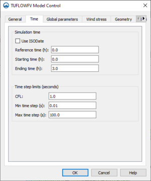
The Time tab of the TUFLOW FV Model Control dialog contains the following options:
- Simulation time
- Use ISODate – Option to use ISODate format which requires data be input in the form dd/mm/yyyy HH:MM:SS. If left off, default time format is hours.
- Reference time – Will set simulation reference time. Times set for starting and ending have reference to this time. This can affect output times when processing and visualizing results from certain programs.
- Starting time – Will set simulation start time.
- Ending time – Will set simulation end time.
- Time step limits
- CFL – Sets the Courant-Friedrichs-Lewy condition. ((This is a control number that gives the model...???)). Can be no larger than one since this is the theoretical stability limit. Often, inputting a value lower than one ensures greater model stability.
- Min time step(s) – Specifies minimum variable time step allowed according to CFL stability criterion.
- Max time step(s) – Specifies maximum variable time step allowed according to CFL stability criterion.
Global parameters
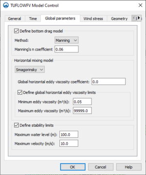
The Global parameters tab of the TUFLOW FV Model Control dialog contains the following options:
- Define bottom drag model – Option to specify bottom drag model for the simulation. The bottom drag model will be used to describe bed boundary resistance in the simulation. The same bottom drag model will be used for every calculation that uses it.
- Method – Option to set bottom drag model to use "Manning" or "KS".
- "Manning" – Uses the Manning model and requires a Manning's n coefficient
- Manning's n coefficient – Sets the Manning's n coefficient.
- "KS" – Uses a model that assumes a log-law velocity profile and requires specification of a surface roughness length-scale.
- Nikuradse roughness – Sets the Nikuradse roughness for the bottom drag model.
- "Manning" – Uses the Manning model and requires a Manning's n coefficient
- Method – Option to set bottom drag model to use "Manning" or "KS".
- Horizontal mixing model – Defines horizontal mixing eddy viscosity calculation according to options in drop-down menu. ((In TUFLOW FV documentation it's called momentum mixing model??)).
- "None" – Will not represent horizontal momentum mixing.
- "Constant" – Option to globally define a specific constant eddy viscosity.
- Global horizontal eddy viscosity – Specifies the constant eddy viscosity for the entire simulation.
- "Smagorinsky" – The horizontal eddy viscosity will be calculated according to the Smagorinsky model which sets the diffusivity proportional to the local strain rate. Requires specification of global horizontal eddy viscosity coefficient.
- Global horizontal eddy viscosity coefficient – Sets the Smagorinsky coefficient for the horizontal mixing eddy viscosity calculation.
- Define global horizontal eddy viscosity limits – Sets for the entire simulation (??Is that what globally means) the limits for the horizontal eddy viscosity values. Only for use with Smagorinsky or Wu models.
- Minimum eddy viscosity – Sets the minimum horizontal eddy viscosity.
- Maximum eddy viscosity – Sets the maximum horizontal eddy viscosity.
- "Wu" – The horizontal eddy viscosity will be calculated according to the Wu model. Requires specification of global horizontal eddy viscosity coefficient. ((Seems to be a wind stress model. Can't figure out what it has to do with the Horizontal Mixing model did it get included here by accident??))
- Global horizontal eddy viscosity – Sets the Wu coefficient for the horizontal mixing eddy viscosity calculation.
- Define global horizontal eddy viscosity limits – Sets the limits for the horizontal eddy viscosity values for the entire simulation. Only for use with Smagorinsky or Wu models.
- Minimum eddy viscosity – Sets the minimum horizontal eddy viscosity.
- Maximum eddy viscosity – Sets the maximum horizontal eddy viscosity.
- Define stability limits – Option to define the maximum acceptable values relevant for the model. If water level or velocity exceed the given values, the model will stop computations and give an error. This feature helps to identify a model with instabilities by recognizing unrealistic values that the model produces. Small anomalies and acceptable spikes in data values will not stop computations.
- Maximum water level – Sets maximum acceptable water level for the model.
- Maximum velocity – Sets maximum acceptable velocity for the model.
Wind stress
The Wind stress tab of the TUFLOW FV Model Control dialog contains the following options:
- Define wind model – Option to define the model used in calculating wind stress for any wind inputs in the simulation.
- Model – Drop-down menu with options for models that can be used to calculate wind stress.
- "Wu" – Sets the wind stress model to the Wu model. Scales wind stress parameterisation based on wind speed.
- "Constant" – Applies wind stress parameterisation using Bulk momentum transfer coefficient as in pre-2019 builds of TUFLOW.
- "Kondo" – Applies a scaling factor ((for the wind stress parameters??)) using a single term.
- Model – Drop-down menu with options for models that can be used to calculate wind stress.
- Define wind parameters – ((Sets the wind drag coefficients that the selected model will use to scale the wind stress parameterisation??)) Varies according to the wind model selected.
- Wa – ((??Wind speed in meters per second))
- Ca –
- Wb –
- Cb –
- Bulk momentum transfer coefficient – Sets the coefficient for the Constant wind stress model.
- Scale factor – Sets the scaling factor for the Kondo wind stress model.
Geometry
The Geometry tab of the TUFLOW FV Model Control dialog contains the following options:
- Define global bed elevation limits – Option to apply bed elevation limits to the entire model. Bed elevations in the model that are outside the set limits will be set to the minimum or the maximum. (Does this change if certain materials are defined contrary to it??))
- Bed elevation minimum – Defines minimum bed elevation. ((Bed Elevations??Maybe just elevations)) in the model below this value will be set to this value.
- Bed elevation maximum – Defines maximum bed elevations. ((Bed Elevations??Maybe just elevations)) in the model above this value will be set to this value.
- Define cell wet/dry depths – Sets the depth limits that define certain attributes of cells in the model.
- Dry depth – Sets a minimum depth value below which the simulation drops a cell from calculations.
- Wet depth – Sets a minimum depth value below which the simulation sets a cell's momentum to zero.
- Z modifications – Options for adjusting and applying elevation data
 Add Row – Adds a row of elevation data to the Z modifications table.
 Delete Row – Deletes the active row of elevation data from the Z modifications table.
 Move up – Moves the selected row of elevation data to be above the row immediately above it.
 Move down – Moves the selected row of elevation data to be below the row immediately below it.
- Type – Option to select which type of elevation input is desired on this row of data. The other columns in the table become active or inactive based on the type selected here.
- Set Zpts – Sets elevation values for the center of all cells in the model domain to the given value.
- GRID Zpts – Interpolates a grid file to set elevations for the mesh cell center. Select (none selected) to open a dialog box and select the desired grid file. Either .asc or .flt. can be used for this feature.
- CSV File – Option to update cell elevations using a .csv file. The .csv file can identify cells using x,y coordinates or cell IDs.
- CSV Type – Select which type of data the .csv file will contain.
- "Cell ID" – Sets the program to read the .csv file data for cell IDs matched with elevation data.
- "Coordinate" – Sets the program to read the .csv file data for x,y coordinates matched with elevation data.
- ZLine Shapes – Sets breakline features and polygon features according to an already imported .shp or .mif/.mid file. Select (none selected) to open a dialog and select the desired file (all RC sees is coverages here, but maybe they are the only things available. They don't seem like any of the described file types??).
- ZPoint Shapes – Sets elevation points according to an already imported .shp or .mif/.mid file. Using this feature, multiple layers of elevation information can be used. This allows for dividing the layers for better data management. Select (none selected) to open the Select Z Point Layers dialog.
Select Z Point Layers
Initial conditions
The Initial conditions tab of the TUFLOW FV Model Control dialog contains the following options:
- Define initial water level – Option set water level to a constant value for the entire simulation. It's best for the water level boundary conditions for the initial time steps to be as close as possible to this setting.
- Use restart file – Option to use a restart file to define the initial conditions for the current run. The restart file must come from a model that uses the same mesh, bathymetry, vertical layering, and number of conserved variables as the model for the current simulation.
- Select... – Opens dialog box for selecting restart file to be used.
- Use restart file time – Option to use the time stamp on the restart file as the starting time of the current run. On by default.
Output
The Output tab of the TUFLOW FV Model Control dialog contains the following options:
- Output blocks – Output blocks set output file types as well as certain output file properties. They also allow for selecting desired datasets to be included in the output file and the time steps at which to output the information.
 Add Row – Adds a output block to the Output blocks table.
 Delete Row – Deletes the selected output block from the Output blocks table.
- "DATV" – SMS will give mapped output in DATV format with user specified datasets and parameters. Often used for data visualization in SMS.
- "XMDF" – SMS will give mapped output in XMDF format with user specified datasets and parameters. Often used for data visualization in SMS.
- "NetCDF" – SMS will give mapped output in NetCDF (network Common Data Form) format with user specified datasets and parameters. Includes mapped output information at the desired time intervals as well as information about model geometry.
- "Flux" – Outputs a CSV file that will give the values of fluid flow and, if applicable, the movement of other quantities that cross model boundaries or other specified nodestrings.
- "Mass" – Outputs a CSV file that can be used to check certain simulated quantities, mainly the volume of fluid within the model domain.
- "Points" – Outputs a CSV file containing model parameter time-series. This includes coordinates and associated data for the points of interest ((as defined in a coverage dedicated to this task.??))
- "Transport" – Outputs a NetCDF file that can be used to improve the runtime of subsequent advection-diffusion, sediment, or particle tracking simulations. It stores conserved variables on the TUFLOW FV mesh for use in future simulations.
- Output block options - Row (value of active row) – Gives options to define attributes and datasets for a selected output block. Many options are only available when certain output blocks are selected. (See table below)
- Output points feature coverage – Only available when a "Points" output block is active. Click Select... to set the coverage that will define the coordinates of the desired output points
- Define Interval – Option to set the interval for the specified output in seconds. If not specified, the program will produce the specified output at every time step, sometimes resulting in output files that are too large.
- Define start time – Sets output request start time. When not specified, the output start time will be the simulation start time. Time format will be the same as format selected under the Time tab.
- Define final time – Sets output request final time. When not specified, the output final time will be the simulation end time. Time format will be the same as format selected under the Time tab.
- Define compression – Option to compress output file.
- Compression on – If turned on, output file will be compressed. On by default.
- Define Statistics – Option to track minimum and/or maximum values of selected datasets.
- Type – Select the values to track from the drop-down menu.
- "Both" – Both maximum and minimum values for selected datasets will be tracked.
- "Minimums" – Only minimum values for selected datasets will be tracked.
- "Maximums" – Only maximum values for selected datasets will be tracked.
- Define statistics dt – Option to define independent output interval for tracking of minimum and maximum values. If not defined, defaults to 0 and uses the model interval.
- Type – Select the values to track from the drop-down menu.
- Filename suffix – Option to specify a desired suffix for output file.
- Datasets – Specify datasets for inclusion in output file. This will only appear when a DATV, XMDF, NetCDF, or points output block is active. For more information, see the table below.
- Directories
- Log directory – Option to specify ((directory??)) for simulation log file (.log) output. When not specified, log file will be written to same location as simulation control file.
- Output directory – Option to specify location in which simulation output files will be written. When not specified, output files will be written to same location as simulation control file.
- Write restart file – TUFLOW FV writes the values of the selected datasets in each cell at desired regular time steps. Specify these time steps in Write restart dt.
- Write restart dt – Specify the desired interval of time steps at which TUFLOW FV will write the restart file.
- Enable restart overwrite – Option to overwrite the restart file being used at the time interval specified in Write restart dt. On by default.
- Write check files – Option to create a number of check files that can be used to verify model inputs.
- Check files directory –
- Write empty GIS files – Option to automatically create GIS template files in .mid/.mif or .shp format with recommended GIS naming conventions that "contain the correct GIS attributes".
- Template files directory – Sets the location in which the empty GIS files will be written.
| Category | Output Block Options | Output blocks that use this option | ||||||||||||
|---|---|---|---|---|---|---|---|---|---|---|---|---|---|---|
|
| ||||||||||||||
| General | ||||||||||||||
| Output points feature coverage | Points | |||||||||||||
| Define interval | DATV, XMDF, NetCDF, Flux, Mass, Points, Transport | |||||||||||||
| Define start time | DATV, XMDF, NetCDF, Flux, Mass, Points, Transport | |||||||||||||
| Define final time | DATV, XMDF, NetCDF, Flux, Mass, Points, Transport | |||||||||||||
| Define compression | XMDF, NetCDF | |||||||||||||
| Define statistics | DATV, XMDF, NetCDF, Flux, Mass, Points, Transport | |||||||||||||
| Filename suffix | DATV, XMDF, NetCDF, Flux, Mass, Points, Transport | |||||||||||||
|
| ||||||||||||||
| Datasets | Water depth | DATV, XMDF, NetCDF, Points | ||||||||||||
| Water surface elevation | DATV, XMDF, NetCDF, Points | |||||||||||||
| Bed shear stress | DATV, XMDF, NetCDF, Points | |||||||||||||
| Surface shear stress | DATV, XMDF, NetCDF, Points | |||||||||||||
| Velocity vector and magnitude | DATV, XMDF, NetCDF, Points | |||||||||||||
| Velocity magnitude only | DATV, XMDF, NetCDF, Points | |||||||||||||
| Bed elevation | DATV, XMDF, NetCDF, Points | |||||||||||||
| Turbulent viscosity | DATV, XMDF, NetCDF, Points | |||||||||||||
| Evaporation rate | DATV, XMDF, NetCDF, Points | |||||||||||||
| Flood hazard category based on the Australian NSW Flood plain management Manual (NSWG, 2005) | DATV, XMDF, NetCDF, Points | |||||||||||||
| Flood hazard category as outlined by Australian Emergency Management Institute in 2014 | DATV, XMDF, NetCDF, Points | |||||||||||||
| Hazard categories for the Queensland Reconstruction Authority | DATV, XMDF, NetCDF, Points | |||||||||||||
| Mean sea level pressure | DATV, XMDF, NetCDF, Points | |||||||||||||
| Downward short-wave radiation flux | DATV, XMDF, NetCDF, Points | |||||||||||||
| Temperatre | DATV, XMDF, NetCDF, Points | |||||||||||||
| 10 m wind speed vector | DATV, XMDF, NetCDF, Points | |||||||||||||
| Wave height – typically significant wave height | DATV, XMDF, NetCDF, Points | |||||||||||||
| Wave period – typically peak wave period | DATV, XMDF, NetCDF, Points | |||||||||||||
| Wave direction | DATV, XMDF, NetCDF, Points | |||||||||||||
| Wave stress vector | DATV, XMDF, NetCDF, Points | |||||||||||||
Source Stuff
Datv (recommended for visualisation in SMS and QGIS). • XMDF (recommended for visualisation in SMS and QGIS). • Flux (time series of fluxes across all nodestrings, refer Section 17.5). • Mass (time series mass in model refer Section 17.5). • NetCDF (cell centred 2D and 3D output, used heavily for 3D model visualisation, refer Section 17.6.4). • Points (time series outputs, refer Section 17.3). • Transport (TUFLOW FV file used for decoupling hydrodynamics from following advection dispersion, sediment or water quality simulations, refer Section 15.8).
The TUFLOW FV ‘DATV’ or ‘XMDF’ options provide output on the mesh nodes at the specified output
time interval.
The TUFLOW FV 2D ‘points’ option provides model parameter time-series at point locations, each defined by a x, y coordinate specified within an output points file.
A file containing the conserved variables stored on the TUFLOW FV mesh to be used in a subsequent advection-diffusion, sediment or particle tracking simulation. Outputs a NetCDF file with conserved variables stored on the TUFLOW FV mesh to be used in subsequent simulations.
Materials
The Materials tab of the TUFLOW FV Model Control dialog contains the following options:
- Define default material (set mat) – ((??Sets the material settings for every cell in the model domain. This material and its attributes will be the assumed material for each cell ((unless a material block defines them otherwise??))
- Override Bottom Roughness – Select to allow for editing bottom roughness of this material.
- Bottom Roughness – Sets the default bottom roughness for the entire model. Will be factored in according to the bottom drag model selected on the Global parameters tab.
- Advanced Options – Select Advanced... to open the Materials (advanced) - Default material (set mat) dialog.
Materials (advanced) - Default material (set mat)
- Define horizontal eddy viscosity – Option to adjust the horizontal eddy viscosity settings for this material. The input asked for here varies depending on the horizontal mixing model selected on the Global Parameters tab.
- Horizontal eddy viscosity – Sets the horizontal eddy viscosity for this material. Only available when Horizontal mixing model under Global Parameters is set to "None" or "Constant".
- Horizontal eddy viscosity coefficient – Sets the coefficient for either the "Wu" or "Smagorinsky" mixing models, depending on the model selected on the Global Parameters tab. Only available when Horizontal mixing model under Global Parameters is set to Smagorinsky or Wu.
- Define bed elevations limits – Option to set limits for the bed elevation of cells defined by this material.
- Minimum bed elevation – Sets minimum bed elevation.
- Maximum bed elevation – Sets maximum bed elevation.
- Spatial reconstruction – Option to limit spatial reconstruction (??for cells that are defined by the default material). This reverts the calculations for this area to first-order calculations in a model that is second-order. This has no effect if the model is already first order as defined in the General tab under Define spatial order.
Boundary Conditions
The Boundary conditions tab of the TUFLOW FV Model Control dialog contains the following options:
- Define BC default update dt – Option to set the time step for all boundary conditions to update. If unspecified, TUFLOW FV will interpolate values to each time step. If specified, TUFLOW FV will keep all values after one update but before the next update at a constant value.
- BC default update dt – ((sets the time value of the time steps that TUFLOW FV will interpolate to??))
- Run in transport mode – Option to run a simulation that includes a transport boundary condition. This option can be useful for later models that use many of the same conditions but require different inputs.
- Transport BC file – Click Select... to set which transport file will be used in this simulation.
- Global boundaries – ((Boundary condition blocks that can be used to apply conditions to every cell in the model domain. For example, it can be used to account for inflow from rain or evaporation.
 Add row – Adds a boundary condition block that specifies conditions over the entire model domain.
 Delete row – Deletes the active global boundary condition block.
- Type – Shows the type of boundary condition assigned to this boundary condition block.
- Attributes
- Assign BC – Opens the Assign Global Boundary Condition dialog.
- Gridded boundaries – So are we applying multiple boundary conditions to the one grid? That's what's happening here??
 Add row – Adds a Gridded BC row to the Gridded boundaries table. Opens the Define BC Grid dialog.
 Delete row – Deletes a Gridded BC row from the Gridded boundaries table.
- Grid Definition
- Define Grid... – Opens Define BC Grid dialog for selecting the grid and associated settings for selected grid definition block.
- Boundaries
- Define BCs... – Opens Add Gridded BCs dialog.
- Global wave options &ndash: Options for use if a linked Boundary Conditions coverage with a wave boundary type and/or a gridded wave boundary defined.
- Include wave stress –
- Include Stokes drift – Option to include Stokes drift in calculations ((Interpolates mass transport for cells between the deepwater and surfzone depth??))
Assign Global Boundary Condition
- Options –
- Type – Sets which type of boundary condition to set globally for the model. The one option is "QG (Global Cell Inflow)".
- "QG (Global Cell Inflow)" – Sets boundary condition as flow into every cell in model domain. Useful to account for effects of rain or evaporation.
- Subtype – Option to adjust how a boundary type functions numerically in the model.
- "Sub-type 1" – The interior model concentration will be used to determine the scalar flux.
- "Sub-type 2" – The value specified in the BC file will determine the scalar flux.
- Define Curve... – Opens "BC Curve Editor" dialog.
- Type – Sets which type of boundary condition to set globally for the model. The one option is "QG (Global Cell Inflow)".
- Define default – Defines default value for a given variable when TUFLOW FV gets a null-value from a boundary condition input.
- Q/A default –
- Define offset – Sets the offset that TUFLOW FV will add to each variable of raw boundary condition data as it is read into TUFLOW FV. Offset will be added to each variable after it is multiplied by the set scale
- Q/A offset –
- Define scale – Sets the scale by which TUFLOW FV will multiply each variable of raw boundary condition data as it is read into TUFLOW FV. The data will be multiplied by the scale before the offset value for each variable is added.
- Q/A scale –
- Define update increment – Sets update intervals of time steps for boundary conditions. When not set, TUFLOW FV will update the boundary condition at every simulation time step.
- Time – The value of the update intervals of time steps.
- Includes mean sea level pressure – Option to specify if an inverse barometer offset is already included in a water level boundary condition. By default, it is on to indicate there is an inverse barometer offset included. If turned off, the difference between the local MSLP and the reference MSLP will be applied at the boundary.
- Define default – Defines default value for a given variable when TUFLOW FV gets a null-value from a boundary condition input.
BC Curve Editor
- Define reference time –
- Use ISODate –
- Reference time –
- Number of rows
- Time Units
- Import...
- Time
- Q/A
 Pan –
Pan –
Define BC Grid
- Grid Definition – Space for defining the location, filename, and settings for a NetCDF file that will be used to map input files to the model mesh.
- File – Click Select... to set the NetCDF file that contains the coordinates that define a grid. The gridded boundary conditions will be applied to this grid.
- Name – Name applied to the grid. Name might be used later to refer to this grid by other boundary conditions in this model.
- NetCDF variables – Sets the variables from the NetCDF file that the program should use to create the grid map.
- X-Variable –
- Y-Variable –
- Z-Variable –
- Define vertical coordinate type – Option to specify the vertical coordinate convention. The different convention names correspond to distinct kinds of depth averaging.
- "Elevation" – [1]. Here is the information. Not sure how to interpret it yet.
- "Depth" –
- "Sigma" –
- "Height" –
- Cell gridmap – When turned off, (I have found info for this, but do not yet know how to rephrase it.)
- Boundary gridmap – If on, calculates (I have found info for this, but do not yet know how to rephrase it.)
- Suppress coverage warnings – Will suppress warnings that indicate the grid does not cover the entire domain.
Add Gridded BCs
This dialog allows for assigning ((??multiple boundary)) conditions to the one grid in the selected row??.
 Add row – Adds a gridded boundary condition block ((to the grid associated with the active grid block??))
 Delete row – Deletes the selected gridded boundary condition block.
- Type – Shows the type of boundary condition grid assigned to this boundary condition block.
- Attributes –
- Assign BC... – Opens Assign Gridded Boundary Condition dialog.
Assign Gridded Boundary Condition
- Options – TUFLOW Manual 15.4.4 BC Scale and BC Offset
- Type – Sets type of boundary condition to be used.
- "MSLP_Grid" – Sets boundary condition type to mean sea level pressure field (grid??).
- "W10_Grid" – Sets boundary condition type to wind velocity at 10m (grid??)) .
- "Wave" –
- Dataset file – Opens dialog to select NetCDF file to define the data for the boundary condition.
- Define Variables – Opens Select NetCDF Gridded BC Variable Names dialog.
- For Define default, Define offset, Define scale, Define reference time, Define time units, and Define update increment, see table below.
- Type – Sets type of boundary condition to be used.
| Grid Type | Option or Variable | Definition | ||||||||||||
|---|---|---|---|---|---|---|---|---|---|---|---|---|---|---|
|
| ||||||||||||||
| All Grids | Define default | Defines default value for a given variable when a boundary condition input gives TUFLOW FV a null-value. | ||||||||||||
| Define offset | Sets the offset that TUFLOW FV will add to each variable of raw boundary condition data as it is read into TUFLOW FV. Offset will be added to each variable after it is multiplied by the set scale. | |||||||||||||
| Define scale | Sets the scale by which TUFLOW FV will multiply each variable of raw boundary condition data as it is read into TUFLOW FV. The data will be multiplied by the scale before the offset value for each variable is added. | |||||||||||||
| Define reference time | Sets reference time for the boundary condition. When not set, the reference time will be the same as the simulation time. Option set reference time in hours, which is the default. Turn on Use ISODate to use that format if desired. | |||||||||||||
| Define time units | Sets time units to be used for the boundary condition. The options are:
| |||||||||||||
| Define update increment | Sets update intervals of time steps for boundary conditions. When not set, TUFLOW FV will update the boundary condition at every simulation time step. | |||||||||||||
| MSLP_Grid | MSLP | Mean sea level pressure | ||||||||||||
| W10_Grid | W10_X | "10 m wind speed vector" | ||||||||||||
| W10_Y | "10 m wind speed vector" | |||||||||||||
| Wave | HSIGN | Significant wave height?? (In TUFLOW FV documentation, it's usually called HSIG except for in Table 15-3.) | ||||||||||||
| TPS | Smoothed peak wave period | |||||||||||||
| DIR | Mean wave direction. This is direction to which waves are heading when the | |||||||||||||
| UBOT | The rms-value (root mean square value?) of the maxima of the orbital velocity near the bottom. If it is left undefined, TUFLOW FV will calculate it using linear wave theory. | |||||||||||||
| TMBOT | The bottom wave period | |||||||||||||
| FORCE_X | X wave induced force vector component (In TUFLOW FV documentation, it's usually called WFORCE_X except for in Table 15-3 | |||||||||||||
| FORCE_Y | Y wave induced force vector component (In TUFLOW FV documentation, it's usually called HSIG except for in Table 15-3.) | |||||||||||||
| DEPTH | Wave model water depth | |||||||||||||
Select NetCDF Gridded BC Variable Names
- Variable names – The variables that appear (other than TIME, which appears no matter which grid type is selected) will be exactly the same as the variables that appear in the Assign Gridded Boundary Condition dialog under Define default, Define offset, and Define scale. It varies depending on the grid type selected.
- TIME variable name – (??Advanced option to select a ??header in the selected file for the TIME variable. Does this vary depending on what file you have selected?
- Grid Specific variables
- MSLP_GRID variables:
- MSLP variable name – Advanced option to select a header in the selected file for the MSLP variable.
- W10_GRID variables:
- W10_X variable name – Advanced option to select a header in the selected file for the W10_X variable.
- W10_Y variable name – Advanced option to select a header in the selected file for the W10_Y variable.
- Wave variables:
- HSIGN variable name – Advanced option to select a header in the selected file for the HSIGN variable.
- TPS variable name – Advanced option to select a header in the selected file for the TPS variable.
- DIR variable name – Advanced option to select a header in the selected file for the DIR variable.
- UBOT variable name – Advanced option to select a header in the selected file for the UBOT variable.
- TMBOT variable name – Advanced option to select a header in the selected file for the TMBOT variable.
- FORCE_X variable name – Advanced option to select a header in the selected file for the FORCE_X variable.
- FORCE_Y variable name – Advanced option to select a header in the selected file for the FORCE_Y variable.
- DEPTH variable name – Advanced option to select a header in the selected file for the DEPTH variable.
- MSLP_GRID variables:
Simulation links
The Simulation links tab of the TUFLOW FV Model Control dialog contains the following options:
 Add row – Brings up the Select Child TUFLOW FV Simulation dialog. In this dialog another TUFLOW FV simulation can be select to link as a child simulation to the current simulation.
 Delete row – Unlinks the selected simulation.
Advanced
The Advanced tab of the TUFLOW FV Model Control dialog contains the option to include advanced options These options can be added in the text editor located in this tab. The text will be appended to the FVC file with the simulation is exported.
Using the Model / Practical Notes
A TUFLOW licence is not required to run a TUFLOW FV model.
External Links
SMS – Surface-water Modeling System | ||
|---|---|---|
| Modules: | 1D Grid • Cartesian Grid • Curvilinear Grid • GIS • Map • Mesh • Particle • Quadtree • Raster • Scatter • UGrid |  |
| General Models: | 3D Structure • FVCOM • Generic • PTM | |
| Coastal Models: | ADCIRC • BOUSS-2D • CGWAVE • CMS-Flow • CMS-Wave • GenCade • STWAVE • WAM | |
| Riverine/Estuarine Models: | AdH • HEC-RAS • HYDRO AS-2D • RMA2 • RMA4 • SRH-2D • TUFLOW • TUFLOW FV | |
| Aquaveo • SMS Tutorials • SMS Workflows | ||
