SMS:Cascade: Difference between revisions
No edit summary |
|||
| (8 intermediate revisions by the same user not shown) | |||
| Line 1: | Line 1: | ||
__NOINDEX__ | |||
{{SMS Deprecated Feature}} | |||
{{TOCright}} | |||
{{Cascade Release}} | {{Cascade Release}} | ||
Cascade is a regional model for calculating coastal sediment transport, | Cascade is a regional model for calculating coastal sediment transport, | ||
morphology change, and sand bypassing at inlets and engineered structures. | morphology change, and sand bypassing at inlets and engineered structures. | ||
| Line 53: | Line 55: | ||
Cascade output solutions consist of shoreline change, sediment transport rates through | Cascade output solutions consist of shoreline change, sediment transport rates through | ||
time and space, average sediment transport rates, and inlet shoal evolution calculated by the inlet reservoir sub-model. | time and space, average sediment transport rates, and inlet shoal evolution calculated by the inlet reservoir sub-model. | ||
== Graphical Interface == | == Graphical Interface == | ||
=== Cascade Menu === | === Cascade Menu === | ||
| Line 104: | Line 104: | ||
* [[SMS:1D Grid Module|1D Grid Module]] | * [[SMS:1D Grid Module|1D Grid Module]] | ||
* [[SMS:GENESIS|GENESIS]] | * [[SMS:GENESIS|GENESIS]] | ||
{{Template:Navbox SMS}} | {{Template:Navbox SMS}} | ||
[[Category:Cascade]] | [[Category:Cascade]] | ||
[[Category:SMS Menus|C]] | [[Category:SMS Menus|C]] | ||
[[Category: | [[Category:Cascade Dialogs|C]] | ||
[[Category:SMS 1D Grid]] | [[Category:SMS 1D Grid]] | ||
[[Category:External Links]] | [[Category:External Links]] | ||
[[Category:Archived]] | |||
Latest revision as of 14:46, 4 June 2019
| This contains information about features no longer in use for the current release of SMS. The content may not apply to current versions. |
This article is for Cascade model. The Cascade model has been replaced by the GenCade model in current editions of SMS.
Cascade is a regional model for calculating coastal sediment transport, morphology change, and sand bypassing at inlets and engineered structures. Cascade is developed by the U.S. Army Engineer Research and Development Center (USACE-ERDC), Coastal and Hydraulics Laboratory (CHL).
Functionality
Cascade simulates shoreline change relative to regional morphologic constraints upon which these processes take place. The evolution of multiple interacting coastal projects and morphologic features and pathways, such as those associated with inlets and adjacent beaches may also be simulated. Cascade, Version 1 calculates wave-induced longshore sediment transport rates, shoreline change, tidal inlet shoal volume evolution, natural bypassing, and the fate of coastal restoration and stabilization projects. It is intended for regional applications, engineering decision support, and long-term morphology response to physical and anthropogenic forcing.
Versions of the Model
The USACE-ERDC team continues to develop the Cascade model using a Spiral Development paradigm. This means that multiple features are being developed as independent capabilities and will be incorporated into a release version of the model when functional and verified.
The current version is version 1. Version 2 and 3 are under construction.
Version Descriptions
| Version | Functionality |
|---|---|
| 1 |
Longshore processes |
| 2 |
Addition of some cross-shore processes. |
| 3 |
Ecological component (habitat and population dynamics) |
Using the Model / Practical Notes
A Cascade grid is created in SMS and initial shoreline and regional shoreline trend may be created in SMS or imported from survey data. Model parameters and spatial and temporal boundary conditions are assigned within the SMS interface. These may include dredge and fill projects, construction of coastal structures, opening of new inlets, shoal and morphologic feature development or equilibrium volumes, wave information forcing, and sediment coefficients and parameters.
Cascade output solutions consist of shoreline change, sediment transport rates through time and space, average sediment transport rates, and inlet shoal evolution calculated by the inlet reservoir sub-model.
Graphical Interface
Cascade Menu
- Attributes
- Film Loop...
- Set Active Coastline
- View Coastline Data
- View Solution Plots
- Create Grid
- Model Control...
- Run Cascade...
Cascade Module Toolbar
- Select Coastline Point
- Create Coastline Point
- Select Dredge/Fill
- Create Dredge/Fill
- Select Grid Cell (also add wave information)
- Edit 1-D Grid
- Select Inlet
- Create Inlet
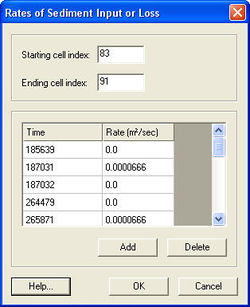
Rates of Sediment Input or Loss
Similar to other time-varying parameters in Cascade, the time listed represents the time at which the condition change. The condition shown at that time is the condition that is valid up to that time from the previous change. In this example, the source has a constant rate of 0.0000666 m2/sec from time step 185640 to 187031 and again from 264480 to 265871.
The user may also redefine the sediment source or sink region by changing the starting and ending cell indices in the top section of the window, in this case cell 83 to 91.
Case Studies / Sample Problems
- Cape Henlopen to Chincoteague Inlet, Delmarva Peninsula, DE/MD/VA
- Fire Island to Montauk Point (FIMP), Long Island, NY
External Links:
- Cascade User Guide: [1]
- Cascade Theory and Model Formulation: [2]
- Inlet Reservoir Model (sub-model within Cascade): [3]
Related Topics
SMS – Surface-water Modeling System | ||
|---|---|---|
| Modules: | 1D Grid • Cartesian Grid • Curvilinear Grid • GIS • Map • Mesh • Particle • Quadtree • Raster • Scatter • UGrid |  |
| General Models: | 3D Structure • FVCOM • Generic • PTM | |
| Coastal Models: | ADCIRC • BOUSS-2D • CGWAVE • CMS-Flow • CMS-Wave • GenCade • STWAVE • WAM | |
| Riverine/Estuarine Models: | AdH • HEC-RAS • HYDRO AS-2D • RMA2 • RMA4 • SRH-2D • TUFLOW • TUFLOW FV | |
| Aquaveo • SMS Tutorials • SMS Workflows | ||
