User:Jcreer/TUFLOW FV for SMS 13.2: Difference between revisions
(→Time) |
|||
| Line 137: | Line 137: | ||
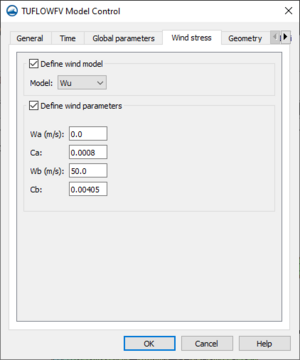
[[File:TUFLOWFV MC Wind.png|thumb|300 px|The ''Wind stress'' tab of the ''TUFLOW FV Model Control'' dialog]] | [[File:TUFLOWFV MC Wind.png|thumb|300 px|The ''Wind stress'' tab of the ''TUFLOW FV Model Control'' dialog]] | ||
The ''Wind stress'' tab of the ''TUFLOW FV Model Control'' dialog contains the following options: | The ''Wind stress'' tab of the ''TUFLOW FV Model Control'' dialog contains the following options: | ||
*Define wind model | *Define wind model – Option to define the model used in calculating wind stress for any wind inputs in the simulation. | ||
**Model | **Model – Drop-down menu with options for models that can be used to calculate wind stress. | ||
***Wu | ***Wu – Sets the wind stress model to the Wu model. Scales wind stress parameterisation based on wind speed. | ||
***Constant | ***Constant – Applies wind stress parameterisation using Bulk momentum transfer coefficient as in pre-2019 builds of TUFLOW. | ||
***Kondo | ***Kondo – Applies a scaling factor ((for the wind stress parameters??)) using a single term. | ||
*Define wind parameters | *Define wind parameters – ((Sets the ((??Wind Drag Coefficients)) parameters that the selected model will use to scale the wind stress parameterisation??)) | ||
**Wa | **Wa – ((??Wind speed in feet per second)) | ||
**Ca | **Ca – | ||
**Wb | **Wb – | ||
**Cb | **Cb – | ||
**Bulk momentum transfer coefficient | **Bulk momentum transfer coefficient – sets the coefficient for the Constant wind stress model. | ||
**Scale factor | **Scale factor – Sets the scaling factor for the Kondo wind stress model. | ||
{{-}} | {{-}} | ||
Revision as of 18:37, 8 February 2022
| TUFLOW FV | |
|---|---|
| Model Info | |
| Model type | Two-dimensional (2D) flexible mesh finite volume flood, tide and water quality simulation software. |
| Developer | WBM BMT WBM (Australia) |
| Web site | www.tuflow.com |
| Tutorials | SMS Learning Center |
TUFLOW FV (which stands for Two-dimensional Unsteady FLOW Finite Volume) is a flexible mesh finite volume numerical model that simulates hydrodynamic, sediment transport and water quality processes in oceans, coastal waters, estuaries and rivers. The model may be used for coastal and nearshore environments including beaches and coastlines as well as offshore environments such as estuaries, river entrances and deltas, and floodplains. Uses include modeling river flood flow, tsunami inundation (the finite-volume scheme is well suited for a tsunami's mixed sub/super-critical flow regimes), beach erosion, ocean pollution, and estuary flow.
Unlike the fixed square grids of TUFLOW Classic, the flexible triangular or quadrilateral mesh of TUFLOW FV allows users to modify mesh resolution spatially, seamlessly increasing the model resolution in areas of interest. This modelling approach reduces the number of computation cells needed in a model reducing run times. Additionally, TUFLOW FV can be run in parallel on multiple processors, threads, or computers.
The TUFLOW FV model can be added to a paid edition of SMS.
TUFLOW FV ENGINE
The TUFLOW computational engine computes 2D hydraulic solutions. The engine uses a macro style text-file input which allows the user to flexibly and efficiently control model configurations and simulations.
For more information see the TUFLOW FV webpage.
SMS Interface
The TUFLOW FV engine is interfaced in SMS through the generic model interface.
TUFLOW FV Coverages
TUFLOW FV simulations require a boundary condition coverage and a materials coverage.
Boundary Conditions Coverage
The TUFLOW FV boundary conditions coverage allows assigning boundary condition attributes to arcs drawn in the coverage. These attributes will then be assigned, or snapped, to the 2D mesh during the simulation run.
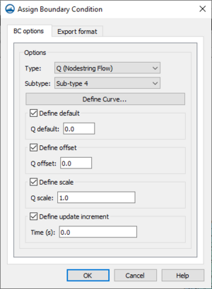
Attributes are assigned to arcs by right-clicking a selected arc and selecting the Assign BC command. This will open the Assign Boundary Condition dialog for TUFLOW FV.
The TUFLOW FV Assign Boundary Condition dialog has the following options:
BC Options – The BC Options tab has options for assigning attributes to the arc.
- Type – The option here determines what type of boundary condition will be assigned to the arc. The following types are available:
- "Monitor" – Sets the arc to be a monitoring line.
- "HQ (Head Discharge)" –
- "Q (Nodestring Flow)"
- "QN (Head Discharge)"
- "WL (Water Level)"
- "WLS (Sloping Water Level"
- "WL_CURT (Water Level Curtain"
- "ZG (Zero Gradient)"
- Subtype
- Define Curve
- Friction slope
- Dataset file
- Define Varaibles
- View Curve
- Define default
- 'Q default
- Define offset
- Q offset
- Define scale
- Q scale
- Define update increment
- Time
- Include mean sea level pressure
Materials
The TUFLOW FV materials coverage allows creating the polygons to hold the material attributes for the simulation run. The assigned material attributes will be mapped to the mesh/grid during the simulation run.
TUFLOW FV Simulation Menu
The TUFLOW FV simulation item in the Project Explorer contains a right-click menu with commands for accessing TUFLOW FV simulation options. The menu has the following commands:
- Simulation Run Queue – Opens the Simulation Run Queue dialog.
- Model Control – Opens the TUFLOWFV Model Control dialog.
- Save Simulation – Saves the simulations and exports the simulations files needed for the simulation run.
- Run Simulation – Runs the simulation using the exported simulation files. will bring up the Simulation Run Queue dialog.
- Save Project, Simulation and Run – Exports the simulation files, saves the project and project files, and runs the simulation. Will bring up the Simulation Run Queue dialog.
- Read Solution – Opens a browser to import the solution files.
- Simulation Properties – Opens the Simulation Propertes dialog where basic information about the simulation can be viewed.
The specific menu commands may be different depending on the selected option in the Preferences dialog.
TUFLOW FV Model Control
The TUFLOW FV Model Control dialog contains options for setting the parameters that will be used during the simulation run. The dialog is accessed by right-clicking on the simulation in the Project Explorer and selecting the Model Control command. The dialog contains multiple options organized on multiple tables. The options are as follows:
General
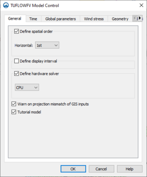
The General tab of the TUFLOW FV Model Control dialog contains the following options:
- Define spatial order – (Option to define horizontal spatial scheme??)
- Horizontal – Select "1st" order scheme or "2nd" order scheme.
- Define display interval – (Does it have something to do with the output interval. Time steps???)
- Display interval
- Define hardware solver – Option to enable computing through the CPU or the GPU. Can produce slight differences in results.
- "CPU" – Calculations will use the "Central Processing Unit".
- "GPU" – Calculations will use the "Graphical Processing Unit". Using GPU with TUFLOW
- Device ID – Option to select which GPU device is used for computers or GPUs with multiple CUDA enabled GPU cards.
- Warn on projection mismatch of GIS inputs – (Sets the program to warn if GIS inputs are not all in the same projection??)
- Tutorial model – (Allows simulation of the TUFLOW Tutorial Models without the need for a TUFLOW license.??)
Time
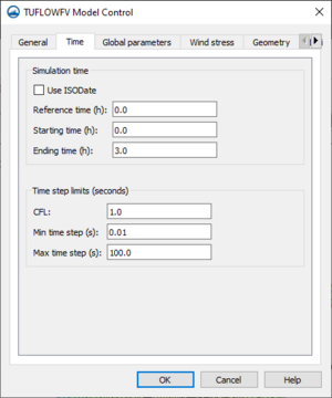
The Time tab of the TUFLOW FV Model Control dialog contains the following options:
- Simulation time
- Use ISODate – Option to use ISODate format which requires data be input in the form dd/mm/yyyy HH:MM:SS. If left off, default time format is hours.
- Reference time – Will set simulation reference time. Times set for starting and ending have reference to this time. This can affect output times when processing and visualizing results from certain programs.
- Starting time – Will set simulation start time.
- Ending time – Will set simulation end time.
- Time step limits
- CFL – Sets the Courant-Friedrichs-Lewy condition. ((This is a control number that gives the model...???)). Can be no larger than one since this is the theoretical stability limit. Often, inputting a value lower than one ensures greater model stability.
- Min time step(s) – ""Specifies minimum variable timestep allowed according to CFL stability criterion""
- Max time step(s) – ""Specifies maximum variable timestep allowed according to CFL stability criterion""
Global parameters
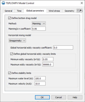
The Global parameters tab of the TUFLOW FV Model Control dialog contains the following options:
- Define bottom drag model – Option to specify bottom drag model for the simulation. The bottom drag model will be used to describe ((bed boundary resistance??)) in the simulation.
- Method – Option to set bottom drag model to use "Manning" or "KS".
- "Manning" – Uses the Manning model and requires a Manning's n coefficient
- Manning's n coefficient – Sets the Manning's n coefficient.
- "KS" – ""Assumes a log-law velocity profile and requires specification of a surface roughness length-scale. Requires "ks" values be set.""
- Nikuradse roughness – Sets the Nikuradse roughness for the bottom drag model.
- "Manning" – Uses the Manning model and requires a Manning's n coefficient
- Method – Option to set bottom drag model to use "Manning" or "KS".
- Horizontal mixing model – ((??Possible Scalar mixing model)) ((Momentum mixing model...?)) Defines horizontal mixing eddy viscosity calculation according to options in drop-down menu.
- "None" – Will not represent horizontal momentum mixing.
- "Constant" – Option to globally define a specific constant eddy viscosity (ft2/s).
- Global horizontal eddy viscosity – Specifies the constant eddy viscosity ((for the entire simulation??).
- "Smagorinsky" – The horizontal eddy viscosity will be calculated according to the Smagorinsky model which sets the diffusivity proportional to the local strain rate. Requires specification of global horizontal eddy viscosity coefficient.
- Global horizontal eddy viscosity coefficient – Sets the Smagorinsky coefficient for the horizontal mixing eddy viscosity calculation.
- Define global horizontal eddy viscosity limits – Sets globally ((for the entire simulation??) the limits for the horizontal eddy viscosity ((values??)). Only for use with Smagorinsky or Wu models.
- Minimum eddy viscosity – Sets the minimum horizontal eddy viscosity in ft2/s.
- Maximum eddy viscosity – Sets the maximum horizontal eddy viscosity in ft2/s.
- "Wu" – The horizontal eddy viscosity will be calculated according to the Wu model. Requires specification of global horizontal eddy viscosity coefficient. ((Seems to be a wind stress model. Can't figure out what it has to do with the Horizontal Mixing model did it get included here by accident??))
- Global horizontal eddy viscosity – Sets the Wu coefficient for the horizontal mixing eddy viscosity calculation.
- Define global horizontal eddy viscosity limits – Sets globally ((for the entire simulation??) the limits for the horizontal eddy viscosity ((values??)). Only for use with Smagorinsky or Wu models.
- Minimum eddy viscosity – Sets the minimum horizontal eddy viscosity in ft2/s.
- Maximum eddy viscosity – Sets the maximum horizontal eddy viscosity in ft2/s.
- Define stability limits – Option to define the maximum acceptable values relevant for the model. If water level or velocity exceed the given values, the model will stop computations and give an error. This feature helps to identify a model with instabilities by recognizing unrealistic values that the model produces. Small anomalies and acceptable spikes in data values will not stop computations.
- Maximum water level – Sets maximum acceptable water level for the model.
- Maximum velocity – Sets maximum acceptable velocity for the model.
Wind stress
The Wind stress tab of the TUFLOW FV Model Control dialog contains the following options:
- Define wind model – Option to define the model used in calculating wind stress for any wind inputs in the simulation.
- Model – Drop-down menu with options for models that can be used to calculate wind stress.
- Wu – Sets the wind stress model to the Wu model. Scales wind stress parameterisation based on wind speed.
- Constant – Applies wind stress parameterisation using Bulk momentum transfer coefficient as in pre-2019 builds of TUFLOW.
- Kondo – Applies a scaling factor ((for the wind stress parameters??)) using a single term.
- Model – Drop-down menu with options for models that can be used to calculate wind stress.
- Define wind parameters – ((Sets the ((??Wind Drag Coefficients)) parameters that the selected model will use to scale the wind stress parameterisation??))
- Wa – ((??Wind speed in feet per second))
- Ca –
- Wb –
- Cb –
- Bulk momentum transfer coefficient – sets the coefficient for the Constant wind stress model.
- Scale factor – Sets the scaling factor for the Kondo wind stress model.
Geometry
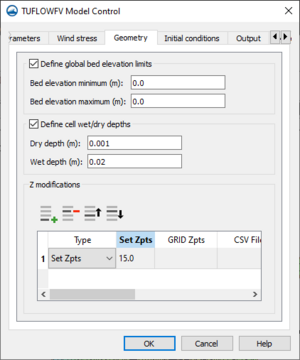
The Geometry tab of the TUFLOW FV Model Control dialog contains the following options:
- Define global bed elevation limits
- Bed elevation minimum
- Bed elevation maximum
- Define cell wet/dry depths
- Dry depth
- Wet depth
- Z modification
- Add Row
- Delete Row
- Move up
- Move down
- Type
- Set Zpts
- GRID Zpts
- CSV File
- CSV Type
- ZLine Shapes
- ZPoint Shapes
Initial conditions
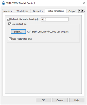
The Initial conditions tab of the TUFLOW FV Model Control dialog contains the following options:
- Define initial water level
- Use restart file
- Select
- Use restart file time
Output
The Output tab of the TUFLOW FV Model Control dialog contains the following options:
Materials
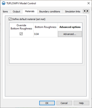
The Materials tab of the TUFLOW FV Model Control dialog contains the following options:
- Define default material (set mat)
- Override Bottom Roughness
- Bottom Roughness
- Advanced Options
Boundary conditions
The Boundary conditions tab of the TUFLOW FV Model Control dialog contains the following options:
- Define BC default update dt
- BC default update dt
- Run in transport mode
- Transport BC file
- Global boundaries
- Add row
- Delete row
- Gridded boundaries
- Add row
- Delete row
- Global wave options
- Include wave stress
- Include Stokes drift
Simulation links
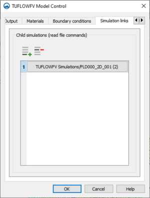
The Simulation links tab of the TUFLOW FV Model Control dialog contains the following options:
- Add row – Brings up the Select Child TUFLOW FV Simulation dialog. In this dialog another TUFLOW FV simulation can be select to link as a child simulation to the current simulation.
- Delete row – Unlinks the selected simulation.
Advanced
The Advanced tab of the TUFLOW FV Model Control dialog contains the option to include advanced options These options can be added in the text editor located in this tab. The text will be appended to the FVC file with the simulation is exported.
Using the Model / Practical Notes
A TUFLOW licence is not required to run a TUFLOW FV model.
External Links
SMS – Surface-water Modeling System | ||
|---|---|---|
| Modules: | 1D Grid • Cartesian Grid • Curvilinear Grid • GIS • Map • Mesh • Particle • Quadtree • Raster • Scatter • UGrid |  |
| General Models: | 3D Structure • FVCOM • Generic • PTM | |
| Coastal Models: | ADCIRC • BOUSS-2D • CGWAVE • CMS-Flow • CMS-Wave • GenCade • STWAVE • WAM | |
| Riverine/Estuarine Models: | AdH • HEC-RAS • HYDRO AS-2D • RMA2 • RMA4 • SRH-2D • TUFLOW • TUFLOW FV | |
| Aquaveo • SMS Tutorials • SMS Workflows | ||
