SMS:General Display Options: Difference between revisions
| Line 54: | Line 54: | ||
==Clip To Clipboard== | ==Clip To Clipboard== | ||
[[File:CopyToClipboard.png|thumb|300 px|The ''Copy To Clipboard'' dialog]] | |||
The ''Copy To Clipboard'' dialog contains options for how the '''Copy to Clipboard''' command works. It can be accessed through the ''Edit'' | '''Copy to Clipboard''' command or through the ''Display Options'' dialog. The dialog has the following options: | The ''Copy To Clipboard'' dialog contains options for how the '''Copy to Clipboard''' command works. It can be accessed through the ''Edit'' | '''Copy to Clipboard''' command or through the ''Display Options'' dialog. The dialog has the following options: | ||
*''Bitmap scale factor'' | *''Bitmap scale factor'' | ||
Revision as of 20:12, 28 March 2022
The General Display options control display of general graphical control. It includes three tabs including:
General Tab
- Drawing Options –
- Z magnification – Exaggerates the z scale so that the variation in the z value is more apparent.
- Background color – Set the background color of the Graphics Window.
- Erase behind labels – Causes SMS to fill the region behind labels such as the contour legend or annotation text with a background colored rectangle. This can prevent the label from being hidden in the rest of the image on the Graphics Window.
- Triad – SMS can display a coordinate triad at the lower left of the screen to display the orientation of the data in the display window. The size and color of this triad can be specified.
- Texture mapping – Currently SMS supports images displayed in the background and texture maps draped over TINS, grids, and meshes.
- Drawing Grid – SMS can display a grid (in plan view) behind all data on the graphics window.
- Grid Spacing – Specifies the increment between grid points. Remember that the grid can be used for both snapping and display, and not all grid lines need to be displayed.
- Snap to Grid – If this option is on, newly created points, nodes and vertices are moved to the nearest point on the grid.
- Display grid lines every n spaces – Enables the display of a line at the select interval. The line style is also selected.
- Display grid points every m spaces – Enables the display of a point at selected intervals along with the symbol attributes for the points.
- Projection Overlay – Controls the display of coordinate system zones in the Graphics Window in the background of the display.
- Enable– Turns on the coordinate system preview option. If the option is enabled, SMS will display the coordinate system zones from the selected group of zones in the background of the Graphics Window. If the display projection is set to Local, this feature can not be enabled. The zones that overlap the current range of the display will be visible.
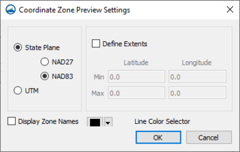
- Configure – Brings up the Coordinate Zone Preview Settings dialog where the display options for the coordinate system preview is set.
Coordinate Zone Preview Settings
The Coordinate Zone Preview Settings dialog has the following options:
- Coordinate system to preview – Choose one of the following:
- State Plane – The U.S. State Plane system using one of the following geodetic datum:
- NAD27
- NAD83
- UTM – The Universal Transverse Mercator coordinate system.
- State Plane – The U.S. State Plane system using one of the following geodetic datum:
- Define Extents – By default SMS will display any coordinate zone from the selected system that overlaps the Graphics Window view. If the Define Extents option is on, specify a range of latitude and longitudes coordinates in the table below. Only coordinate zones that lie in that subrange will be displayed.
- Display Zone Name – Gives the option to display the zone label name along with the coordinate system boundary.
- Line Color Selector – Chooses the color to display the boundaries of the visible coordinate zones using the color picker or clicking on the box to being up the Select Color dialog.
Lighting Tab
The Lighting tab accesses the Lighting Options in SMS.
View Tab
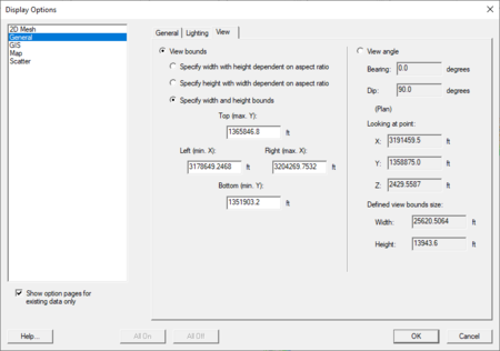
The View tab in the general display options allows editing the current view parameters. This includes the specification of the type of view (plan or 3D) and the range of the data that is displayed on the screen.
The view parameters can be set in two ways: View bounds or View angle.
View bounds is used for 2D viewing. The minimum and maximum X (left/right) and Y (top/bottom) dimensions for the display in the graphics window can be set. The dimension that can be set depends on which of the following options are set:
- Specify width with height dependent on aspect ratio
- Specify height with width dependent on aspect ratio
- Specify width and height bounds
View angle is used for 3D viewing. It allows setting the following options:
- Bearing
- Dip
- Looking at point – This section allows defining a point for the center of the display. Set the X, Y, and Z values for this point.
- Define view bounds size – This section allows defining the viewing bounds of the display. Set the Width and Height of the boundary area.
Clip To Clipboard
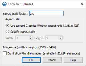
The Copy To Clipboard dialog contains options for how the Copy to Clipboard command works. It can be accessed through the Edit | Copy to Clipboard command or through the Display Options dialog. The dialog has the following options:
- Bitmap scale factor
- Aspect ratio
- Use current Grpahics Window aspect ration
- Specify aspect ration
- Width
- Height
- Image size
- Don't show this dialog again
Related Topics
SMS – Surface-water Modeling System | ||
|---|---|---|
| Modules: | 1D Grid • Cartesian Grid • Curvilinear Grid • GIS • Map • Mesh • Particle • Quadtree • Raster • Scatter • UGrid |  |
| General Models: | 3D Structure • FVCOM • Generic • PTM | |
| Coastal Models: | ADCIRC • BOUSS-2D • CGWAVE • CMS-Flow • CMS-Wave • GenCade • STWAVE • WAM | |
| Riverine/Estuarine Models: | AdH • HEC-RAS • HYDRO AS-2D • RMA2 • RMA4 • SRH-2D • TUFLOW • TUFLOW FV | |
| Aquaveo • SMS Tutorials • SMS Workflows | ||


