AHGW:What's New in AHGW 2.3.0: Difference between revisions
(Created page with "The more significant new features in Arc Hydro Groundwater 2.3.0 are listed below. ==Arc GIS 9.3 Required== The new Arc Hydro Groundwater toolkit now requires Arc GIS versi...") |
m (Jmonson moved page Test:What's New in AHGW 2.3.0 to AHGW:What's New in AHGW 2.3.0 without leaving a redirect) |
(No difference)
| |
Latest revision as of 21:29, 12 September 2019
The more significant new features in Arc Hydro Groundwater 2.3.0 are listed below.
Arc GIS 9.3 Required
The new Arc Hydro Groundwater toolkit now requires Arc GIS version 9.3, starting at version 2.1. Previous version of Arc Hydro Groundwater supported both Arc GIS 9.2 and 9.3.
Groundwater Analyst
A new tool was added for creating Arc Hydro Groundwater geodatabases.
Create Blank AHGW Geodatabase
This tool creates a new Arc Hydro Groundwater geodatabase, filled with empty tables and feature classes that conform to the Arc Hydro Groundwater data model. This includes tables and feature classes for Groundwater Analyst, MODFLOW Analyst, and Subsurface Analyst. The fields in the tables and feature classes are populated based on the groundwater configuration file. This tool can be used to explore the various groundwater data models, or import existing data found in other formats.
Subsurface Analyst
Subsurface Analyst includes two new tools for working with XS2D plots.
Transform Faults to XS2D Lines
This tool transforms geologic fault data from 3D space to XS2D space along a SectionLine feature. The tool works off of a point feature class that includes information about the direction in which the fault dips, the angle from horizontal in which the fault dips, and how far the fault line extends. The tool intersects the fault with a SectionLine feature, and converts that intersection into XS2D space. When digitizing XS2D_Panel features, the resulting XS2D fault lines can be used as a guide to edit your subsurface data.
Create XS2D Log Feature Classes
This tool creates XS2D_LogPlot features classes for adding geophysical data to an XS2D data frame. The tool creates three feature classes representing geophysical data (point, line and polygon) and five feature classes representing the scale and grid. Additional tools for adding geophysical log plots will be developed in the future.
Import XS2D Image Wizard
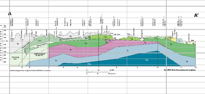
This wizard allows you to take a background image of a cross section, such as from a geologic map, and register it in a new XS2D data frame for creating cross section panel features.
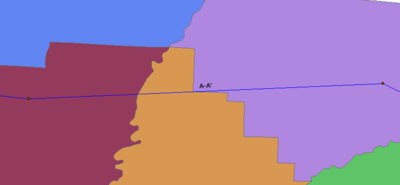
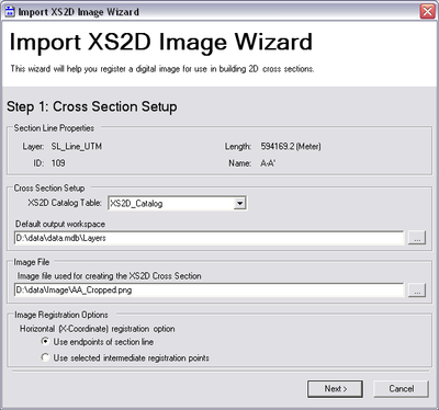
With a SectionLine feature in the map representing the location of your cross section panel, you first bring up the wizard and specify the geodatabase and XS2D_Catalog table to write to, along with the image file to use. You are also given the option to specify the X coordinates of the image registration based on the endpoints of the Section Line feature, or two intermediate points such as an outcropping or other point of interest on the map.
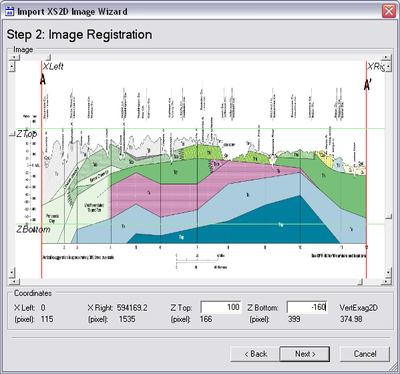
Once the image has been chosen, you specify the points used to register the image into the XS2D space. The red lines specify the beginning and ending of the Section Line feature (or the two intermediate points if you chose that option), while the green lines are used for two known elevations. The elevation values are entered in the edit fields at the bottom of the wizard.
The wizard then walks you through a couple of steps to optionally set up feature classes for cross section panels, panel dividers, and major and minor grids. Suggested values such as the grid extent and the number of major and minor tick values can be entered by clicking on a button, based on the image registration options.
Once the wizard has completed, a new data frame will be created in Arc Map for your Section Line. The image file you specified will show up, registered based on the coordinates and values entered in by the wizard. Cross section panels and major and minor grid lines will also be created. At this point, you can start creating cross section panel polygon features by starting an edit session and using the background image as a guide.
MODFLOW Analyst
MODFLOW Analyst includes support for the MNW1 (Multi-Node, Drawdown-Limited Well) Package, and new tools for creating geodatabases in the MODFLOW Data Model format.
MNW1 Package Support
The import tools found in MODFLOW Analyst now support reading in the MNW1 package. Data is stored in new tables. Variables associated with the MNW1 package are stored in the MNW1Vars table, while the individual wells are stored in the MNW1 table.
Export Package MNW1
This new tool exports a MNW1 package file.
Import Georeferenced MODFLOW Model
This tool imports a MODFLOW Model which has been georeferenced by a MODFLOW World File, into a new geodatabase that conforms to the MODFLOW Data Model. MODFLOW data files will be imported as tables in the geodatabase. The Boundary, Cell2D and Node2D feature classes will be created, along with the CellIndex table. The coordinate system of the feature dataset created for these features is determined by reading the MODFLOW World file. An Arc Hydro Groundwater configuration file (.gwd file) will be created.
This tool allows you to quickly set up and populate a MODFLOW Data Model geodatabase from only MODFLOW simulation files, and is the preferred tool for importing MODFLOW data, and is the recommended way to import MODFLOW data using the Arc Hydro Groundwater toolkit.
Unlike previous tools to import MODFLOW data, you do not need to create a new geodatabase, feature dataset, and groundwater configuration file in advance. As long as you have a MODFLOW solution with a MODFLOW world file, you can quickly generate a new MODFLOW Data Model geodatabase without the hassle of any additional setup.
Create MODFLOW World File
This tool creates a new MODFLOW World File, which is used to georeference a MODFLOW model. The world file specifies the origin, rotation and spatial reference of a MODFLOW Model. The origin specifies the point that locates the MODFLOW grid origin, where i = 0 and j = 0.
See also


