The 3D Grid module is used to create 3D Cartesian grids. These grids can be used for interpolation, isosurface rendering, cross sections, and finite difference modeling.
Interfaces to the following 3D finite difference models are provided in this module:

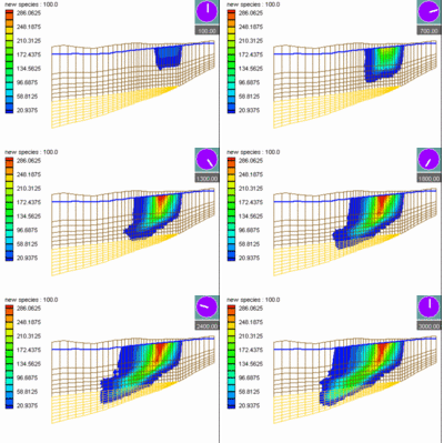
Sample MT3D Simulation
The 3D Grid tools are included with all editions of GMS, including the community version.
3D Grid Types
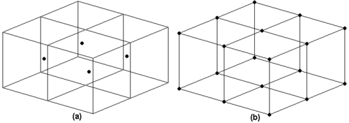
Two types of 3D grids are supported in GMS: cell centered and mesh centered. When computations are performed on a mesh-centered grid, the computation points are the grid nodes or the corners of the grid cells. With a cell-centered grid, computations are performed at the cell centers. The display options, however, shows both cell- and mesh-centered grids as having the node dots on the corners of the cells.
When a dataset is imported to a cell-centered grid, there is one value in the dataset for each cell. To use contouring or fringing the values at the cell corners must be known. Therefore, whenever contouring or fringing is performed, the values at the cell centers are interpolated to the cell corners. Interpolation to cell corners is only done for visualization. All computations performed using the Data Calculator are performed on the original values at the cell centers. With mesh-centered grids, all visualization and computations are performed at the cell corners and no interpolation is necessary.
All of the model interfaces in the 3D Grid module are based on cell-centered grids. Mesh-centered grids are useful for interpolation and isosurface visualization since no extra interpolation is necessary.

(a) Cell Centered Grid (b) Mesh Centered Grid
3D Grid Properties
In the Project Explorer, right-click on the 3D grid and select Properties to view a dialog containing information about the grid, such as the grid type and number of cells.


