GMS:Converting 3D Grids to Other Data Types
3D grid data can be converted to other types of data in GMS such as 2D grids, 2D scatter points, 3D meshes, or 3D scatter points. 3D grid data is converted using the following commands in the Grid menu:
Contents
Grid → 3D Scatter Points
The Grid → Scatter Points command in the Grid menu in the 3D Grid module is used to create a new scatter point set using the nodes or cells of a 3D grid. A copy is made of each of the datasets associated with the grid and the datasets are associated with the new scatter point set.
Grid → 3D Mesh
A new 3D finite element mesh can be created from a 3D grid by selecting the Grid → Mesh command from the Grid menu in the 3D Grid menu. An eight node quadrilateral element is created from each cell in the grid.
Grid → 2D Grid
A new 2D grid can be created from a 3D grid by selecting the Grid → 2D Grid command from the Grid menu in the 3D Grid module. This creates a 2D grid which matches the 3D grid, i.e., one cell is created in the 2D grid for each vertical (ij) column in the 3D grid. This command is typically used in conjunction with the 3D Data → 2D Data command.
Grid → UGrid
A new unstructured grid can be created from a 3D grid by selecting the Grid → UGrid command from the Grid menu. The new Ugrid will use the dimension of the 3D grid.
MODFLOW Layers → 2D Scatter Points
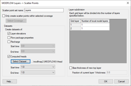
The MODFLOW Layers → 2D Scatter Points command in the Grid menu of the 3D Grid module is used for regional to local model conversion. It is only available if the true layer mode is being used with a MODFLOW model. When this command is selected, a new 2D scatter point set is created and a scatter point is created at the centroid of each vertical column of cells in the 3D grid. A dataset is then created on the scatter point set for the top and bottom elevations of each layer and for the computed head values (if a MODFLOW solution is in memory). The MODFLOW head data set is chosen in the following way: If a modflow head dataset is the active dataset then GMS uses that dataset for the starting heads. If the active dataset is in a modflow solution but is not a head dataset then GMS tries to use the head dataset in the active solution. If neither of the first 2 cases works then GMS just goes through the list of datasets and uses the last modflow head dataset that it finds (most likely the last solution that was read in). At a later point in time, these datasets can be interpolated from the scatter points to the cell centers of a smaller, local grid.
This dialog allows creating a scatter point set and datasets of the current MODFLOW simulation.
The process can limit the number of scatter points created by turning on the Only create scatter points within selected coverage option and selecting the appropriate coverage. This is often used when converting between a regional model and a local scale model.
- Layer Subdivision
- The layers of the current MODFLOW simulation can be subdivided by specifying the Number of local model layers for each layer in the current 3D grid.
- Select which MODFLOW datasets to create by turning off/on the toggles below the Create datasets of text. Datasets for layer elevations, flow package data (HK, HANI, VK, SY, SS...), Recharge, and Heads can be created. The user must select a 3D grid dataset in order to create a dataset for the Heads (most often this will be the MODFLOW solution from the regional model).
- The Recharge and Head datasets can be transient if the regional model was transient. The user can also select a Start and End time to limit the number of time steps for these datasets.
- Bias Layer 1
- An option to bias the thickness of the new layer 1 is also available. This can be useful if equally subdividing layer 1 of the regional model would result in cells where the elevation would be above the computed heads. Thus, the user can choose to bias the thickness of the new layer 1 to ensure that the top layer in the new model will not be dry.
3D Data → 2D Data
The 3D Data → 2D Data command in the Data menu of the 3D Grid module is used to create datasets on a 2D grid created using the Grid to 2D Grid command. These two commands are useful for creating a 2D representation of a 3D dataset for contouring.
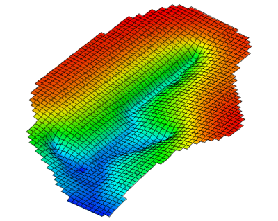
The 3D Data → 2D Data command brings up the 3D Dataset → 2D Dataset dialog. The button at the top of the dialog is used to select which 3D dataset is to be converted to a 2D dataset. The drop down box lists each of the options available for converting each column of 3D data values to a single 2D data value. The figure below shows an example of using the 3D Data → 2D Data command.
| [hide]GMS – Groundwater Modeling System | ||
|---|---|---|
| Modules: | 2D Grid • 2D Mesh • 2D Scatter Point • 3D Grid • 3D Mesh • 3D Scatter Point • Boreholes • GIS • Map • Solid • TINs • UGrids | |
| Models: | FEFLOW • FEMWATER • HydroGeoSphere • MODAEM • MODFLOW • MODPATH • mod-PATH3DU • MT3DMS • MT3D-USGS • PEST • PHT3D • RT3D • SEAM3D • SEAWAT • SEEP2D • T-PROGS • ZONEBUDGET | |
| Aquaveo | ||


