AHGW:2D Cross Section Wizard: Difference between revisions
From XMS Wiki
Jump to navigationJump to search
Tag: Rollback |
No edit summary |
||
| Line 1: | Line 1: | ||
{{TOC right}} | {{TOC right}} | ||
==ArcGIS Notes== | |||
The ''2D Cross Section Wizard'' dialog is accessed by clicking [[File:AHGW XS2D Wizard Icon.png]] '''2D Cross Section Wizard''' on the [[AHGW:Arc Hydro Groundwater Toolbar|Arc Hydro Groundwater Toolbar]]. This tool helps create a new data frame in which to display a 2D cross section for the selected section line in [[ArcGIS]]. | The ''2D Cross Section Wizard'' dialog is accessed by clicking [[File:AHGW XS2D Wizard Icon.png]] '''2D Cross Section Wizard''' on the [[AHGW:Arc Hydro Groundwater Toolbar|Arc Hydro Groundwater Toolbar]]. This tool helps create a new data frame in which to display a 2D cross section for the selected section line in [[ArcGIS]]. | ||
Revision as of 22:12, 8 January 2024
ArcGIS Notes
The 2D Cross Section Wizard dialog is accessed by clicking ![]() 2D Cross Section Wizard on the Arc Hydro Groundwater Toolbar. This tool helps create a new data frame in which to display a 2D cross section for the selected section line in ArcGIS.
2D Cross Section Wizard on the Arc Hydro Groundwater Toolbar. This tool helps create a new data frame in which to display a 2D cross section for the selected section line in ArcGIS.
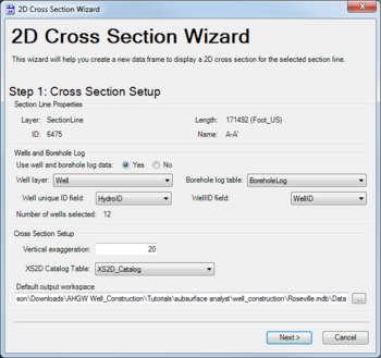
There are three pages to this dialog:
- Step 1: Cross Section Setup
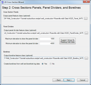
- Step 2: Cross Sections Panels, Panel Dividers, and Borelines
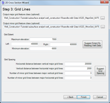
- Step 3: Grid Lines
Cross Section Setup
The following sections, options, and fields are available:
- Section Line Properties section – Not user editable. Lists attributes of the selected section line.
- Wells and Borehole Log section
- Use well and borehole log data – Select Yes or No. Selecting "no" allows the user to proceed without selecting any wells.
- Well layer – Select the desired layer from the drop-down.
- Well unique ID field – Select the field to use as the well unique ID field. Default value is "HydroID".
- Borehole log table – Select the desired table from the drop-down.
- WellID field – Select the field to use as the WellID field. Default value is WellID.
- Number of wells selected – Displays the quantity of wells selected. If no wells are selected, may display a warning to the right of the quantity value.
- Cross Section Setup section
- Vertical exaggeration – Enter a decimal value for the amount of vertical exaggeration in the display of the information.
- XS2D Catalog Table – Select the table from the drop-down.
- Default output workspace – Displays the absolute path to the output workspace. Click
 to bring up the Select Output Workspace dialog where a new output workspace can be created.
- Next – Switches to the second page of the 2D Cross Section Wizard dialog.
- Cancel – Cancels any changes and exits the 2D Cross Section Wizard dialog.
Cross Sections Panels, Panel Dividers, and Borelines
The following sections, options, and fields are available:
- Cross Section Panels section – An optional path for Output panel feature class. Click
 to bring up the Save Panel Features As dialog where a new feature class can be entered and saved. A default value will already be populated.
 - Panel Dividers section – An optional path for Output panel divider feature class. Click
 to bring up the Save Panel Divider Features As dialog where a new feature class can be entered and saved. A default value will already be populated.
- Maximum elevation to draw the panel divider – Enter a decimal maximum elevation value.
- Minimum elevation to draw the panel divider – Enter a positive or negative decimal minimum elevation value.
- Suggest Values by Reading Well Data – Click to populate the above two fields with suggested values based on the well data being used.
- Borelines section – An optional path for Output boreline feature class. Click
 to bring up the Save Boreline Features As dialog where a new feature class can be entered and saved. A default value will already be populated.
- Create borelines from well and borehole log data – Select Yes or No.
- Back – Switches back to the first page of the 2D Cross Section Wizard dialog.
- Next – Switches to the third page of the 2D Cross Section Wizard dialog.
- Cancel – Cancels any changes and exits the 2D Cross Section Wizard dialog.
Grid Lines
The following sections, options, and fields are available:
- Output major grid feature class – An optional path. Click
 to bring up the Save Major Grid Features As dialog where a new feature class can be entered and saved. A default value will already be populated.
 - Output minor grid feature class – An optional path. Click
 to bring up the Save Minor Grid Features As dialog where a new feature class can be entered and saved. A default value will already be populated.
 - Grid Extent section – Contains four fields, listed clockwise from the top, and a button:
- Maximum elevation – A decimal value for the maximum elevation of the grid.
- Right – A decimal value for the right extent of the grid.
- Minimum elevation – A decimal value for the minimum elevation of the grid.
- Left – A decimal value for the left extent of the grid.
- Suggest Extent by Reading Well Data – Click to populate the above four fields with suggested values based on the well data being used.
- Grid Spacing section
- Horizontal distance between vertical major grid lines – Decimal value.
- Vertical distance between horizontal major grid lines – Decimal value.
- Number of minor grid lines between major vertical grid lines – Integer value.
- Number of minor grid lines between major horizontal grid lines – Integer value.
- Suggest Grid Spacing – Click to populate the above four fields with suggested values based on the grid dimensions.
- Back – Switches back to the second page of the 2D Cross Section Wizard dialog.
- Finish – Saves the values and closes the 2D Cross Section Wizard dialog.
- Cancel – Cancels any changes and exits the 2D Cross Section Wizard dialog.


