SMS:Mesh Module
The 2D Mesh Module is used to manipulate 2D unstructured grids (referred to as a mesh inside of SMS). A mesh consists of nodes that are grouped together to form elements. These nodes and elements define the computational domain of the numerical model. In addition to nodes and elements, a mesh may assign additional information to the nodes and elements, such as material values assigned to elements and boundary conditions assigned to nodes. In general, this additional information is used as input data for the numerical model.
Nodes
Nodes are the basic building blocks of elements in a mesh. Nodes store elevation and other data set values. Nodes can also be used for building nodestrings and assigning boundary conditions. The density of mesh nodes helps determine the quality of solution data and can be important to model stability. More
Elements
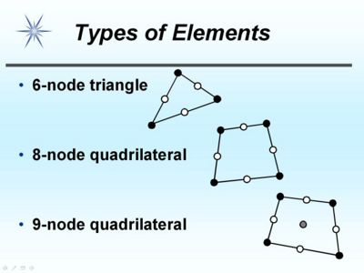
Elements are used to describe the area to be modeled. Elements are formed by joining nodes. The element types supported vary from model to model. Element types include:
1D elements
- Three-node line
Triangular Elements
- Three-node linear triangule
- Six-node quadratic triangle
Quadratic (order of solution) Elements
- Eight-node “serendipity” quadrilateral
- Nine-node “Lagrangian” quadrilateral
Water surface and ground elevations are interpolated linearly within each element based on values at the corner nodes. Velocity is interpolated using a quadratic approximation based on values at all the nodes of the element. The quadrilateral elements use identical linear interpolation functions, but their quadratic functions differ because of the presence of an additional node at the center of the nine-node quadrilateral element.
Mesh Datasets
Datasets in a mesh store scalar or vector values at each node. Dataset Active/Inactive areas (generally indicating wet vs dry areas) can be defined on elements or be determined from specific NULL values (often -999) on the nodes themselves. Datasets are used for input data primarily for bathymetry values. Datasets are generally the primary output from a numeric model. Datasets are used with visualization options such as contours and vectors as well as data extraction tools like observation profile plots.
Node/Element properties
In addition to datasets, nodes and elements sometimes need to store additional information generally for model setup. The most common example of this is material types which are assigned to elements.
Nodestrings
A collection of nodes can be formed into a nodestring. Nodestrings are most commonly used to assign boundary conditions such as a flowrate or water-surface elevation. Nodestrings can also be used for mesh renumbering, forcing break lines, and boundary smoothing. Finally, a nodestring can store attributes pertinent to a location such as the total flow nodestring.
Mesh Generation
See Mesh Generation for more information.
Editing a Mesh
Whenever practical a mesh should be reconstructed from a conceptual model rather than edited in the mesh module. Often this isn't an option and a mesh must be edited by hand. The 2D Mesh Module Tools are used to create and edit meshes within the mesh module.
Mesh Visualization
After an analysis, output data at each node of the mesh can be used to generate linear or color filled contours as well as display vector arrows to visualize model solutions. Animations can be generated that shows changes through time for a time-varying solution. Meshes can also be used with flowtrace and multiple view animations.
Advantages of a Mesh
Meshes and other types of unstructured grids (such as TINs) have the advantage they can include a wide range of element sizes and transition gradually between them. Coastal models are often extreme examples of this sometimes with elements as small as a few meters and as large as many kilometers in the same domain. This allows a very large domain while keeping model computation time to a reasonable level.
Mesh Models
SMS has interfaces to several models that use meshes for computations and boundary conditions. These include:
In addition to the models with complete interfaces, the mesh module contains the Generic Model interface which allows users to customize SMS to generate data for a user defined model.
The finite difference model TUFLOW uses meshes for post-processing but not for building model domains.
Current Numerical Model
The mesh module is set up to be used with a single numerical model analysis engine at any given time. The current numerical model is changed using the Data Menu, Switch Current Model menu command. SMS shows only those tools in the tool palette and those menus in the Menu Bar which are relevant to the current numerical model. After a finite element mesh has been read, boundary conditions and material properties can be assigned using the commands in the menus associated with the current numerical model. The current model on startup can be changed in the Preferences Dialog.
Mesh Module Tools
See Mesh Module Tools for more information.
Mesh Module Menus
See 2D Mesh Module Menus for more information.
Related Topics
- Creating 2D Meshes
- Editing 2D Meshes
- 2D Mesh Generation
- Mesh Data Menu
- Mesh Module Display Options
- SMS Modules
Modules: Mesh Module · Cartesian Grid Module · Scatter Module · Map Module · GIS Module · Particle Module
Models: ADCIRC · BOUSS-2D · CGWAVE · CMS-Flow · CMS-Wave · FESWMS · FVCOM · Generic Mesh Model · GENESIS · HYDRO AS-2D · PTM · SRH-2D · Steering · STWAVE · TABS · TUFLOW
