|
|
| Line 14: |
Line 14: |
| Once the 2D mesh is created, the next step is to create the 3D mesh by extruding each of the 2D elements into a series of 3D elements. The elevations of the 3D elements can be defined from a set of boreholes, a set of TINs, or a set of Solids. | | Once the 2D mesh is created, the next step is to create the 3D mesh by extruding each of the 2D elements into a series of 3D elements. The elevations of the 3D elements can be defined from a set of boreholes, a set of TINs, or a set of Solids. |
|
| |
|
| For sites with relatively simple stratigraphy, the [[GMS:Boreholes#Converting Borehole Data|'''''Regions -> 3D Mesh''''']] command in the Borehole module can be used. | | For sites with relatively simple stratigraphy, the [[GMS:Converting Borehole Data|'''''Regions -> 3D Mesh''''']] command in the Borehole module can be used. |
|
| |
|
| For sites with more complex stratigraphy, the Fill Between [[GMS:TIN Module#Building Solids and 3D Meshes with TINs|'''''TINs -> 3D Mesh''''']] command in the TIN module should be used. | | For sites with more complex stratigraphy, the Fill Between [[GMS:TIN Module#Building Solids and 3D Meshes with TINs|'''''TINs -> 3D Mesh''''']] command in the TIN module should be used. |
Once the FEMWATER conceptual model is constructed, the next step is to use the conceptual model to build a 3D finite element mesh. This is accomplished by first building a 2D mesh, then building the 3D mesh by extruding each of the 2D elements in 3D elements.
Map -> 2D Mesh
The first step in building the 3D mesh is to select the Map -> 2D Mesh command in the Feature Objects menu. This command creates a 2D mesh by automatically filling in the interior of the conceptual model with nodes and elements. The size and spacing of the elements is controlled by the spacing of the vertices on the arcs and by the refine point attribute assigned to any wells in the interior of the conceptual model.
An example of the Map -> 2D Mesh command is shown in the following figure. A sample FEMWATER conceptual model is shown in part a. The 2D mesh resulting from execution of the Map -> 2D Mesh command is shown in part b.
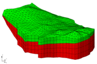
File:Meshgenc.gif Converting a FEMWATER Conceptual Model (a) Conceptual Model (b) 2D Mesh Created with Map -> 2D Mesh Command (c) 3D Mesh Created by Extruding 2D Mesh (d) 3D Mesh after Map -> FEMWATER Command.
Creating the 3D Elements
Once the 2D mesh is created, the next step is to create the 3D mesh by extruding each of the 2D elements into a series of 3D elements. The elevations of the 3D elements can be defined from a set of boreholes, a set of TINs, or a set of Solids.
For sites with relatively simple stratigraphy, the Regions -> 3D Mesh command in the Borehole module can be used.
For sites with more complex stratigraphy, the Fill Between TINs -> 3D Mesh command in the TIN module should be used.
A mesh can also be created using the Solids -> Layered Mesh command in the Solid module.
