User:Jcreer/SMS:ADCIRC Model Control in SMS 13.0: Difference between revisions
| Line 120: | Line 120: | ||
***Increment | ***Increment | ||
**Meteorological | **Meteorological | ||
***Ouput Format | ***Ouput Format | ||
***Append on hot start | ***Append on hot start | ||
Revision as of 15:44, 9 October 2018
The ADCIRC Model Control dialog is where important project parameters are chosen and defined. The six different tabs are listed below.
- General Parameters – Contains such options as model type, cold/hot start, terms, maximum number of iterations, bottom stress/friction, etc.
- Model Formulation
- Timing – Defines simulation run time, start time, and time step options
- Output
- Wind – Enables specific wind types and their options
- Nodal Attributes
- Harmonics Analysis – Defines tidal constituents and harmonic analysis options
- Wind – Enables specific wind types and their options
General Tab

The General parameters tab contains the following:
- Simulation description –
- Project title
- Run ID
- Run options
- Hot start file (initial conditions) – This option allows choosing a file to initialize the values of water level and velocity for a simulation. The files must have been saved from a previous run using the same finite element grid. Default is "None: cold start". Other options are for specific file types containing the initial conditions for the model. Select the desired file type and the Select button will appear. Using the Select button will bring up a browser window to select the hot start file.
- Run parallel ADCIRC
- Bottom stress/friction – NOLIBF –
- "Linear bottom friction "
- Friction coefficient – The "Linear" option should only be used for analytical cases when verifying the code. Linear friction causes overdamping in deep water. For "Constant Quadratic" the value of TAU0 should be set based on the principle depth. A value of TAU0 = 0.005 is suggested for deeper water (greater than 10 m depth). For shallow water, TAU0 = 0.02 is recommended. If the domain includes both shallow and deep water, consider the varying quadratic option.
- "Quadratic bottom friction "
- Friction coefficient – The "Linear" option should only be used for analytical cases when verifying the code. Linear friction causes overdamping in deep water. For "Constant Quadratic" the value of TAU0 should be set based on the principle depth. A value of TAU0 = 0.005 is suggested for deeper water (greater than 10 m depth). For shallow water, TAU0 = 0.02 is recommended. If the domain includes both shallow and deep water, consider the varying quadratic option.
- "Hybrid nonlinear bottom friction"
- Friction coefficient
- Break depth
- Approach factor
- Increase factor
- "Quadratic friction nodal attributes – Fric"
- Select
- "Mannings N nodal attributes – ManningsN"
- Select
- "Chezy C nodal attribute – ChezyFric"
- Select
- "Linear bottom friction "
- Coordinates
- Coriolis option – Constant, Variable. The type of Coriolis forcing used does not impact run time for ADCIRC at all. Variable should be used when the coordinate system is geographic. In this case, ADCIRC will load a Coriolis coefficient for each node based on the latitude of the node. If wanting to run ADCIRC in rectilinear coordinates, specify a constant Coriolis option because the model does not support reprojection from rectilinear to geographic to determine individual latitudes for each node.
- Calculate SLAM0 and SFEA0 on export
- Flow boundaries
- Minimum angle for tangential flow
- Logging
- Auto-correct (non-fatal erro override) – NFOVER
- Logging level
- Log message output (negative values output to file)
____
- Initial Values – Cold Start, Hot Start 1, Hot Start2. This option allows choosing a file to initialize the values of water level and velocity for a simulation. The files must have been saved from a previous run using the same finite element grid.
- Minimum Angle For Tangential Flow
- Terms – Finite Amplitude Terms, Advective Terms, Time Derivative Terms
- Wetting/Drying – Activating this option will cause an Options button to appear. Clicking this button will bring up the Wetting/Drying Parameters dialog.
- Solver Type – Lumped, Direct Banded, Iterative JCG – The Iterative JCG is the default and recommended solver. The other options are in the interface for backward compatibility and analytic tests.
- Absolute Convergence Criteria
- Maximum Number of Iterations per Time Step
- Generalized Properties – Wave Continuity, Lateral Viscosity
Model Formulation Tab

- Model Type
- "Barotropic 2DDI"
- "Barotropic 3D"
- "Baroclinic 3D"
- "Barotropic 2DDI using lumped GWCE (explicit)"
- "Barotropic 3D using lumped GWCE (explicit)"
- Nonlinear terms
- Finite amplitude terms
- Minimum depth
- Minimum vel
- Advective terms – NOLICA
- Advection state nodal attribute
- Generalized wave continuity equation
- Weighting factor
- Time weighting factors
- Solver option
- Solver message level
- Absolute convergence
- Maximum number of iterations
Timing Tab
The Timing tab contains the following options:
- Timing
- Time step
- Length of run
- Ramp Options – NRAMP
- Number of hyperpoic tangent spin up ramps
- Duration
- General Ramp
- External flux ramp
- Flux setting time
- Internal flux ramp
- Specified WSE ramp
- Tidal potential ramp
- Wind/Pressure ramp
- Wave stress ramp
- Delay
- Ramp Function Value – This value is a period of time, starting at the beginning of a simulation, that allows the full forcing of the tidal constituents to be gradually applied to the model. This prevents any issues or negative effects from occurring that could harm the results of a simulation.[1]
- Reference time – Specifies that the extracted tidal constituents are earlier or later than the start time of the simulation (see ADCIRC documentation Reftime).
- Start Day – The start time of a project
- Time Step – Time interval between successive measurements
- Run Time – Total length of time a simulation is run
- End Time – Day when simulation should finish

Output Tab

- Global output
- Water surface elevation
- Output format
- Append on hot start
- Start
- End
- Increment
- Velocity
- Ouput Format
- Append on hot start
- Start
- End
- Increment
- Meteorological
- Ouput Format
- Append on hot start
- Start
- End
- Increment
- Water surface elevation
- Recording stations
- Water surface elevation
- Velocity
- Meteorological
- Hot start input
- Format
- Increment
Wind Tab

ADCIRC can model and compute wind velocities and stresses. The ADCIRC model is able to use wind data from a variety of different file types. The SMS interface is not able to read and create all of the available wind data file types. There are three types that SMS is able to read and create. Even though SMS does not read and create these other file types, it does tell ADCIRC that there is data there, where it is, and how to access it for a simulation to run correctly.
One of the parameters found in the fort.22 file (Single File Meteorological Forcing Input File) will tell which of the wind data file types SMS can read and create. The first parameter specified in the fort.22 file is called the Node Wind Stress (NWS) value. This value represents what type of wind data is in the file. It can range from 0 to 100+. SMS can read and create fort.22 files that are of the NWS value of 1, 2, or 5. All other values of the NWS value are only shown and directed to the ADCIRC model by SMS so that a simulation will run correctly.
Nodal Attributes Tab
- Surface submergence state
- Sea surface height above geoid
- Wave refraction in swan
- Bridge pilings friction parameters
- Elemental slope limiter
- Initial river elevation
Harmonics Analysis Tab

Tidal constituents are variations in tides that are created by different frequencies of astronomical forcing. They arise due to the gravitational influences of the Moon and Sun on the Earth, the tilt of the rotational axis of the Earth, the elliptical shape of the Moon's orbit around the Earth, the shape of the Earth's orbit around the Sun, and other such factors. Many constituents have been defined and are classified based on their cycle lengths. Most of the tidal constituents used in the ADCIRC interface of SMS are either diurnal (one cycle per day) or semidiurnal (two cycles per day) in nature. Harmonic constituents are those variations that have periods of less than half a day. For a table of commonly used constituents see Principal Tidal Constituents.[1]
SMS uses the following databases to provide the tidal constituent data to an ADCIRC simulation:
- LeProvost – The LeProvost database is a set of *.legi files which provide amplitude and phase information. The LeProvost database can be downloaded at: sms.aquaveo.com/leprovost.zip.
- An image of the LeProvost tidal database domain coverage can be found here –
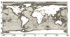 [2]
[2]
- An image of the LeProvost tidal database domain coverage can be found here –

- ADCIRC – The ADCIRC database includes a grid file and a harmonics file that uses an *.exe extractor to put information into SMS. The ADCIRC database can be downloaded at: sms.aquaveo.com/adcirctides.zip. More information about the ADCIRC database can be obtained at the ADCIRC web page: ADCIRC Tides Databases. The ADCIRC database is only valid for projections in North America.
The path to each database on a computer must be specified in the Preferences dialog by going to Edit | Preferences then selecting the File Locations tab. The two tidal constituent databases (LeProvost and ADCIRC) are only accessible if the SMS project has a global (not local) display projection.
Advanced Controls
- Changing bathymetry
- Use hostrarted fort.141
- Domain
- Update increment
- Increment duration

References
- ^ a b Militello, A., and Zundel, A. K. (1999). “Surface-water modeling system tidal constituents toolbox for ADCIRC,” Coastal Engineering Technical Note CETN IV-21, U.S. Army Engineer Research and Development Center, Vicksburg, MS.
- ^ Le Provost, C., Genco, M. L., and Lyard, F. (1995). “Modeling and predicting tides over the World Ocean,” Quantitative Skill Assessment for Coastal Ocean Models, Coastal and Estuaring Studies, Vol. 47, pp 175-201.
Related Links
- ADCIRC
- Boundary Conditions
- Coverage
- Linear Truncation Error Analysis (LTEA)
- Meshes
- Spatial Attributes
- Steering
SMS – Surface-water Modeling System | ||
|---|---|---|
| Modules: | 1D Grid • Cartesian Grid • Curvilinear Grid • GIS • Map • Mesh • Particle • Quadtree • Raster • Scatter • UGrid |  |
| General Models: | 3D Structure • FVCOM • Generic • PTM | |
| Coastal Models: | ADCIRC • BOUSS-2D • CGWAVE • CMS-Flow • CMS-Wave • GenCade • STWAVE • WAM | |
| Riverine/Estuarine Models: | AdH • HEC-RAS • HYDRO AS-2D • RMA2 • RMA4 • SRH-2D • TUFLOW • TUFLOW FV | |
| Aquaveo • SMS Tutorials • SMS Workflows | ||