User:Rcorrigan/AHGW Pro:Create XS2D Cross Section: Difference between revisions
(Created page with "__NOINDEX__ {{TOC right}} The ''2D Cross Section Wizard'' pane is accessed by clicking File:AHGW XS2D Wizard Icon.png '''2D Cross Section Wizard''' on the AHGW:Arc Hydro...") |
No edit summary |
||
| Line 1: | Line 1: | ||
__NOINDEX__ | __NOINDEX__ | ||
{{TOC right}} | {{TOC right}} | ||
The '' | The ''Create XS2D Cross Section'' tool is accessed by clicking [[File:AHGW XS2D Wizard Icon.png]] '''Create 2D Cross Section''' on the [[AHGW:Arc Hydro Groundwater Toolbar|Arc Hydro Groundwater Ribbon]]. This tool helps create a new data frame in which to display a 2D cross section for the selected SectionLine in ArcGIS Pro. | ||
There are three pages to this dialog: | There are three pages to this dialog: | ||
| Line 8: | Line 8: | ||
*Step 3: Grid Lines | *Step 3: Grid Lines | ||
==Cross Section Setup== | The following sections, options, and fields are available: | ||
*''Section Line'' section – Gives tools for selecting the desired SectionLine. Also, lists attributes of the selected SectionLine. | |||
**''SectionLine Layer'' – Select the desired SectionLine layer from the drop-down. | |||
**[[File:Arcgispro Slct.png|16 px]] – Select this icon to activate the select tool. Then, left-click on the SectionLine feature that will be used to create the XS2D cross section feature. Once the SectionLine is selected, its attributes will appear in the ''ID'', ''Length'', and ''Name'' fields. | |||
*''Wells and Borehole Log'' section | |||
**''Use well and borehole log data'' – Checking the checkbox turns on using well and borehole log data. Unchecking the checkbox allows the user to proceed without selecting any wells. | |||
**''Well layer'' – Select the desired layer from the drop-down. | |||
***Well unique ID field – Select the field to use as the well unique ID field. Default value is "HydroID". | |||
**''Number of wells selected'' – Displays the quantity of wells selected. If no wells are selected, may display a warning to the right of the quantity value. | |||
**''Boreholelog Table'' – Select the desired table from the drop-down. | |||
***WellID field – Select the field to use as the WellID field. Default value is WellID. | |||
*''Cross Section Setup'' section | |||
**''Vertical exaggeration'' – Enter a decimal value for the amount of vertical exaggeration in the display of the information. | |||
**''XS2D Catalog Table'' – Select the table from the drop-down. | |||
*''Panel Divider Elevations'' section – Use the table in this section to define the maximum and minimum elevation values used to draw the panel dividers. | |||
**''Minimum'' – Enter a positive or negative decimal minimum elevation value. | |||
**''Maximum'' – Enter a decimal maximum elevation value. | |||
**'''Suggest Values from Well Data''' – Click to populate the above two fields with suggested values based on the well data being used. | |||
*''Borelines'' section | |||
**''Create borelines from well and borehole log data'' – Turn on or off using the checkbox. | |||
*''Grid Extent'' section – Contains four fields and a button: | |||
**''Top'' – A decimal value for the maximum elevation of the grid. | |||
**''Bottom'' – A decimal value for the minimum elevation of the grid. | |||
**''Left'' – A decimal value for the left extent of the grid. | |||
**''Right'' – A decimal value for the right extent of the grid. | |||
**'''Suggest Grid Extent''' – Click to populate the above four fields with suggested values based on the well data being used. | |||
*''Grid Spacing'' section | |||
**''Distance between major grid lines'' | |||
***''Horizontal'' – Decimal value for horizontal distance between vertical major grid lines. | |||
***''Vertical'' – Decimal value for vertical distance between horizontal major grid lines. | |||
**''Number of minor grid lines'' | |||
***''Vertical'' – Integer value for number of minor grid lines between major vertical grid lines. | |||
***''Horizontal'' – Integer value for number of minor grid lines between major horizontal grid lines. | |||
**'''Suggest Grid Spacing''' – Click to populate the above four fields with suggested values based on the grid dimensions. | |||
*'''Create XS2D Data''' – Runs the ''Create XS2D Cross Section'' tool. The tool uses the information entered to create an XS2D data frame representing the features entered. Once the XS2D data frame has been created, ArcGIS Pro drawing tools can be used to digitize a cross section. | |||
==ArcGIS Notes== | |||
The ''2D Cross Section Wizard'' pane is accessed by clicking [[File:AHGW XS2D Wizard Icon.png]] '''2D Cross Section Wizard''' on the [[AHGW:Arc Hydro Groundwater Toolbar|Arc Hydro Groundwater Toolbar]]. This tool helps create a new data frame in which to display a 2D cross section for the selected SectionLine in [[ArcGIS]]. | |||
There are three pages to this dialog: | |||
*Step 1: Cross Section Setup | |||
*Step 2: Cross Sections Panels, Panel Dividers, and Borelines | |||
*Step 3: Grid Lines | |||
===Cross Section Setup=== | |||
[[File:AHGW 2D Cross Section Wizard dialog Step 1.png|350px|thumb|right|The ''Step 1'' page of the ''2D Cross Section Wizard'' dialog]] | [[File:AHGW 2D Cross Section Wizard dialog Step 1.png|350px|thumb|right|The ''Step 1'' page of the ''2D Cross Section Wizard'' dialog]] | ||
The following sections, options, and fields are available: | The following sections, options, and fields are available: | ||
*''Section Line Properties'' section – Not user editable. Lists attributes of the selected | *''Section Line Properties'' section – Not user editable. Lists attributes of the selected SectionLine. | ||
*''Wells and Borehole Log'' section | *''Wells and Borehole Log'' section | ||
**''Use well and borehole log data'' – Select ''Yes'' or ''No''. Selecting "no" allows the user to proceed without selecting any wells. | **''Use well and borehole log data'' – Select ''Yes'' or ''No''. Selecting "no" allows the user to proceed without selecting any wells. | ||
| Line 26: | Line 72: | ||
*'''Cancel''' – Cancels any changes and exits the ''2D Cross Section Wizard'' dialog. | *'''Cancel''' – Cancels any changes and exits the ''2D Cross Section Wizard'' dialog. | ||
==Cross Sections Panels, Panel Dividers, and Borelines== | ===Cross Sections Panels, Panel Dividers, and Borelines=== | ||
[[File:AHGW 2D Cross Section Wizard dialog Step 2.png|350px|thumb|right|The ''Step 2'' page of the ''2D Cross Section Wizard'' dialog]] | [[File:AHGW 2D Cross Section Wizard dialog Step 2.png|350px|thumb|right|The ''Step 2'' page of the ''2D Cross Section Wizard'' dialog]] | ||
The following sections, options, and fields are available: | The following sections, options, and fields are available: | ||
| Line 40: | Line 86: | ||
*'''Cancel''' – Cancels any changes and exits the ''2D Cross Section Wizard'' dialog. | *'''Cancel''' – Cancels any changes and exits the ''2D Cross Section Wizard'' dialog. | ||
==Grid Lines== | ===Grid Lines=== | ||
[[File:AHGW 2D Cross Section Wizard dialog Step 3.png|350px|thumb|right|The ''Step 3'' page of the ''2D Cross Section Wizard'' dialog]] | [[File:AHGW 2D Cross Section Wizard dialog Step 3.png|350px|thumb|right|The ''Step 3'' page of the ''2D Cross Section Wizard'' dialog]] | ||
The following sections, options, and fields are available: | The following sections, options, and fields are available: | ||
Revision as of 19:49, 29 August 2022
The Create XS2D Cross Section tool is accessed by clicking ![]() Create 2D Cross Section on the Arc Hydro Groundwater Ribbon. This tool helps create a new data frame in which to display a 2D cross section for the selected SectionLine in ArcGIS Pro.
Create 2D Cross Section on the Arc Hydro Groundwater Ribbon. This tool helps create a new data frame in which to display a 2D cross section for the selected SectionLine in ArcGIS Pro.
There are three pages to this dialog:
- Step 1: Cross Section Setup
- Step 2: Cross Sections Panels, Panel Dividers, and Borelines
- Step 3: Grid Lines
The following sections, options, and fields are available:
- Section Line section – Gives tools for selecting the desired SectionLine. Also, lists attributes of the selected SectionLine.
- SectionLine Layer – Select the desired SectionLine layer from the drop-down.
 – Select this icon to activate the select tool. Then, left-click on the SectionLine feature that will be used to create the XS2D cross section feature. Once the SectionLine is selected, its attributes will appear in the ID, Length, and Name fields.
- Wells and Borehole Log section
- Use well and borehole log data – Checking the checkbox turns on using well and borehole log data. Unchecking the checkbox allows the user to proceed without selecting any wells.
- Well layer – Select the desired layer from the drop-down.
- Well unique ID field – Select the field to use as the well unique ID field. Default value is "HydroID".
- Number of wells selected – Displays the quantity of wells selected. If no wells are selected, may display a warning to the right of the quantity value.
- Boreholelog Table – Select the desired table from the drop-down.
- WellID field – Select the field to use as the WellID field. Default value is WellID.
- Cross Section Setup section
- Vertical exaggeration – Enter a decimal value for the amount of vertical exaggeration in the display of the information.
- XS2D Catalog Table – Select the table from the drop-down.
- Panel Divider Elevations section – Use the table in this section to define the maximum and minimum elevation values used to draw the panel dividers.
- Minimum – Enter a positive or negative decimal minimum elevation value.
- Maximum – Enter a decimal maximum elevation value.
- Suggest Values from Well Data – Click to populate the above two fields with suggested values based on the well data being used.
- Borelines section
- Create borelines from well and borehole log data – Turn on or off using the checkbox.
- Grid Extent section – Contains four fields and a button:
- Top – A decimal value for the maximum elevation of the grid.
- Bottom – A decimal value for the minimum elevation of the grid.
- Left – A decimal value for the left extent of the grid.
- Right – A decimal value for the right extent of the grid.
- Suggest Grid Extent – Click to populate the above four fields with suggested values based on the well data being used.
- Grid Spacing section
- Distance between major grid lines
- Horizontal – Decimal value for horizontal distance between vertical major grid lines.
- Vertical – Decimal value for vertical distance between horizontal major grid lines.
- Number of minor grid lines
- Vertical – Integer value for number of minor grid lines between major vertical grid lines.
- Horizontal – Integer value for number of minor grid lines between major horizontal grid lines.
- Suggest Grid Spacing – Click to populate the above four fields with suggested values based on the grid dimensions.
- Distance between major grid lines
- Create XS2D Data – Runs the Create XS2D Cross Section tool. The tool uses the information entered to create an XS2D data frame representing the features entered. Once the XS2D data frame has been created, ArcGIS Pro drawing tools can be used to digitize a cross section.
ArcGIS Notes
The 2D Cross Section Wizard pane is accessed by clicking ![]() 2D Cross Section Wizard on the Arc Hydro Groundwater Toolbar. This tool helps create a new data frame in which to display a 2D cross section for the selected SectionLine in ArcGIS.
2D Cross Section Wizard on the Arc Hydro Groundwater Toolbar. This tool helps create a new data frame in which to display a 2D cross section for the selected SectionLine in ArcGIS.
There are three pages to this dialog:
- Step 1: Cross Section Setup
- Step 2: Cross Sections Panels, Panel Dividers, and Borelines
- Step 3: Grid Lines
Cross Section Setup
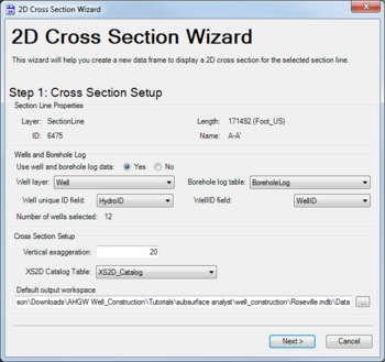
The following sections, options, and fields are available:
- Section Line Properties section – Not user editable. Lists attributes of the selected SectionLine.
- Wells and Borehole Log section
- Use well and borehole log data – Select Yes or No. Selecting "no" allows the user to proceed without selecting any wells.
- Well layer – Select the desired layer from the drop-down.
- Well unique ID field – Select the field to use as the well unique ID field. Default value is "HydroID".
- Borehole log table – Select the desired table from the drop-down.
- WellID field – Select the field to use as the WellID field. Default value is WellID.
- Number of wells selected – Displays the quantity of wells selected. If no wells are selected, may display a warning to the right of the quantity value.
- Cross Section Setup section
- Vertical exaggeration – Enter a decimal value for the amount of vertical exaggeration in the display of the information.
- XS2D Catalog Table – Select the table from the drop-down.
- Default output workspace – Displays the absolute path to the output workspace. Click
 to bring up the Select Output Workspace dialog where a new output workspace can be created.
- Next – Switches to the second page of the 2D Cross Section Wizard dialog.
- Cancel – Cancels any changes and exits the 2D Cross Section Wizard dialog.
Cross Sections Panels, Panel Dividers, and Borelines
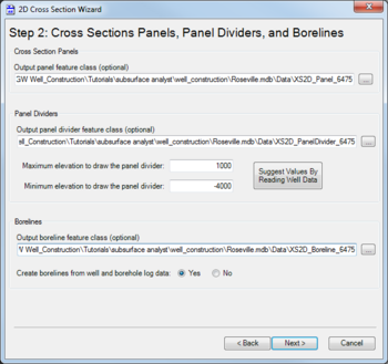
The following sections, options, and fields are available:
- Cross Section Panels section – An optional path for Output panel feature class. Click
 to bring up the Save Panel Features As dialog where a new feature class can be entered and saved. A default value will already be populated.
 - Panel Dividers section – An optional path for Output panel divider feature class. Click
 to bring up the Save Panel Divider Features As dialog where a new feature class can be entered and saved. A default value will already be populated.
- Maximum elevation to draw the panel divider – Enter a decimal maximum elevation value.
- Minimum elevation to draw the panel divider – Enter a positive or negative decimal minimum elevation value.
- Suggest Values by Reading Well Data – Click to populate the above two fields with suggested values based on the well data being used.
- Borelines section – An optional path for Output boreline feature class. Click
 to bring up the Save Boreline Features As dialog where a new feature class can be entered and saved. A default value will already be populated.
- Create borelines from well and borehole log data – Select Yes or No.
- Back – Switches back to the first page of the 2D Cross Section Wizard dialog.
- Next – Switches to the third page of the 2D Cross Section Wizard dialog.
- Cancel – Cancels any changes and exits the 2D Cross Section Wizard dialog.
Grid Lines
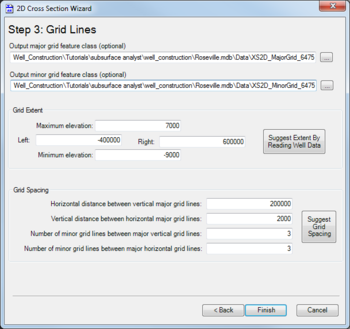
The following sections, options, and fields are available:
- Output major grid feature class – An optional path. Click
 to bring up the Save Major Grid Features As dialog where a new feature class can be entered and saved. A default value will already be populated.
 - Output minor grid feature class – An optional path. Click
 to bring up the Save Minor Grid Features As dialog where a new feature class can be entered and saved. A default value will already be populated.
 - Grid Extent section – Contains four fields, listed clockwise from the top, and a button:
- Maximum elevation – A decimal value for the maximum elevation of the grid.
- Right – A decimal value for the right extent of the grid.
- Minimum elevation – A decimal value for the minimum elevation of the grid.
- Left – A decimal value for the left extent of the grid.
- Suggest Extent by Reading Well Data – Click to populate the above four fields with suggested values based on the well data being used.
- Grid Spacing section
- Horizontal distance between vertical major grid lines – Decimal value.
- Vertical distance between horizontal major grid lines – Decimal value.
- Number of minor grid lines between major vertical grid lines – Integer value.
- Number of minor grid lines between major horizontal grid lines – Integer value.
- Suggest Grid Spacing – Click to populate the above four fields with suggested values based on the grid dimensions.
- Back – Switches back to the second page of the 2D Cross Section Wizard dialog.
- Finish – Saves the values and closes the 2D Cross Section Wizard dialog.
- Cancel – Cancels any changes and exits the 2D Cross Section Wizard dialog.


