SMS:Mesh Tools Coverage
| This feature is currently in Beta release for SMS Some features and capabilities are still in development for SMS. |
The coverage needs to be set to the Mesh Tools type. In a Mesh Tools coverage there are several tools available for editing meshes using the Map module. These tools are found by right-clicking a Mesh Tools coverage in the Project Explorer and going to the Tools submenu.
Polygons from Features
This tool will generate polygons from included features. An arc must be in the coverage for this. Set the features to be included by checking the box next to Include this feature when creating polygons in the Channel/Embankment Properties dialog for the feature. This will create a new Generated polygons coverage to to hold the new polygons.
Do not include arcs that are connected as those will cause overlapping polygons, which will give an error and not properly generate.
Trim Coverage from Polygons
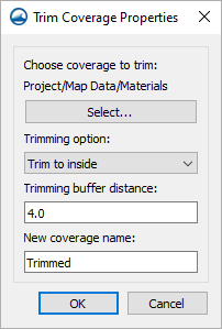
After creating a polygon in the Mesh Tools coverage, this tool is used to remove everything that is not wanted inside or outside the polygon. The dialog has the following options:
- Choose coverage to trim Select... – This will bring up the Select Feature Coverage dialog, where a feature coverage to trim can be selected.
- Trimming option – This is a drop-down that contains two options for trimming:
- "Trim to inside" – Feature objects will be inside the polygon.
- "Trim to outside" – Keep feature objects that are outside the polygon.
- Trimming buffer distance – A value can be entered for the trimming buffer distance.
- New coverage name – A name can be entered for the new trim coverage.
Merge Meshes
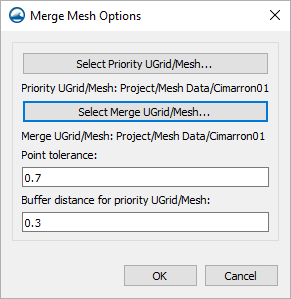
This allows merging two meshes, UGrids, or scatter sets together. The dialog has the following options:
- Select Priority UGrid/Mesh... – This will bring up the Select UGrid/Mesh dialog where the priority UGrid or Mesh can be selected.
- Select Merge UGrid/Mesh... – This will bring up another Select UGrid/Mesh dialog where this time the merge UGrid or Mesh can be selected.
- Point tolerance – A value can be entered for the point tolerance.
- Buffer distance for priority UGrid/Mesh – A value for the buffer distance of the priority UGrid or Mesh can be entered.
Channel/Embankment Properties
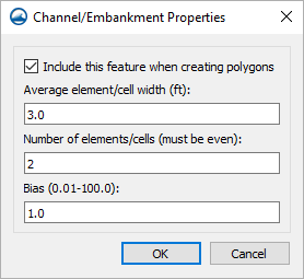
The following dialog can be accessed by right-clicking a selected arc and selecting the Assign Properties... command. The dialog has the following options:
- Include this feature when creating polygons – This is a checkbox that when selected, will include the selected feature when creating polygons.
- Average element/cell width (ft) – A value can be entered for the average width of elements or cells (in feet).
- Number of elements/cells (must be even) – A value can be entered for the amount of elements and cells (which must be even).
- Bias (0.01-100.0) – A value can be entered for the bias, ranging from 0.01 to 100.0.
Related Topics
| [hide] SMS – Surface-water Modeling System | ||
|---|---|---|
| Modules: | 1D Grid • Cartesian Grid • Curvilinear Grid • GIS • Map • Mesh • Particle • Quadtree • Raster • Scatter • UGrid |  |
| General Models: | 3D Structure • FVCOM • Generic • PTM | |
| Coastal Models: | ADCIRC • BOUSS-2D • CGWAVE • CMS-Flow • CMS-Wave • GenCade • STWAVE • WAM | |
| Riverine/Estuarine Models: | AdH • HEC-RAS • HYDRO AS-2D • RMA2 • RMA4 • SRH-2D • TUFLOW • TUFLOW FV | |
| Aquaveo • SMS Tutorials • SMS Workflows | ||


