SMS:TUFLOW Flow Constriction Shapes
Flow constrictions are of two categories: standard (non-layered) and layered flow constrictions. Layered flow constrictions can be used to model situations where flow has multiple pathways at different elevations. Examples would include flow under a bridge and over the bridge deck as well as a pipeline (typically large box culverts to model as 2D) crossing a waterway. The standard (non-layered) flow constrictions can model box culverts, floating bridge decks, bridges, or apply additional form losses to an area (due to submodel scale features). Flow constrictions can be created for arcs or polygons.
Standard (non-layered) Flow Constrictions
Flow constrictions introduce additional losses and/or reduced flow areas through an area of the domain. Flow constrictions can be used for large box culverts, bridges, or floating bridge decks. Flow constriction properties include invert elevations (optional), low chord (obvert) elevations for structures, blockage information, manning n values, and form loss coefficients.
Layered Flow Constrictions
Here is the description from the TUFLOW manual:
Four layers (not GIS layers!) are represented, with the bottom three layers each having their own attributes. The top, fourth, layer assumes the flow is unimpeded (eg. flow over the top of a bridge). Within the same shape, the invert of the bed, and thickness of each layer can vary in 3D. Each layer is assigned its own percentage blockage and form loss coefficient. For example, the layers of a bridge structure would be along the following lines.
- Layer 1: Beneath the bridge deck. Might be 5% blocked due to the bridge piers and have a small form loss for the energy losses associated with the piers.
- Layer 2: The bridge deck. This would be 100% blocked and the form loss coefficient would increase due to the additional energy losses associated with flow surcharging the deck.
- Layer 3: The bridge rails. These might be anything from 100% blocked (solid concrete rails) to 10% blocked (very open rails). Some form losses would be specified depending on the type of rails.
- Layer 4: Flow over the top of the rails – flow assumed to be unimpeded.
Layered FCs function by adjusting the flow width of the 2D cell so as to represent the combination of blockages of the four layers, and by accumulating the form losses. When the flow is only within Layer 1, only the attributes of Layer 1 are applied. As the water level rises into Layer 2, the influence of the Layer 2 attributes increase as the water continues to rise. Similarly for Layer 3 and Layer 4.
The cell side flow width is calculated by summing the flow areas of each layer (including the effects of layer blockages), and dividing by the water depth. The form losses are applied as follows:
- If the water is entirely within Layer 1, the Layer 1 FLC is applied.
- If the water level has reached Layer 2, the value applied is the Layer 1 FLC plus a fraction of the Layer 2 FLC based on the depth of water within Layer 2. For example, if Layer 1 FLC is 0.1 and Layer 2 is 0.5, and the water is 40% of the way up Layer 2, the FLC applied is 0.1 + 0.4*0.5 = 0.3.
- Similarly, if the water level is into Layer 3, the FLC is the Layer 1 FLC plus the Layer 2 FLC plus a fraction of the Layer 3 FLC.
- Once the water level is above Layer 3, ie. is into Layer 4, the FLC is held constant at the sum of the FLCs for Layers 1 to 3.
--TUFLOW Manual 2008-08
Varying Elevations Within Flow Constriction
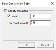
Flow constrictions can be specified as polygons or arcs (along a line). For a flow constriction defined by a polygon, some values may be varied within the polygon by using arc and point attributes. For standard flow constrictions, the invert and low chord (obvert) elevations can be modified within the polygon. For layered flow constrictions, the layer elevations, blockage, form losses, and invert elevations can vary within the polygon.
In order to distribute these vertices for the flow constriction, TUFLOW creates a TIN from the specified data points and interpolates these values through the flow constriction. The flow constriction dialog has several attributes which influence how this TIN is generated and applied. The final elevations for the grid can be verified by reading the "zsh_zpt_check.mif" file into the GIS coverage. The final information about standard flow constrictions can be verified using check files. The "fcsh_uvpt_check.mif" for standard flow constrictions and "lfcsh_uvpt_check.mif" for layered flow constrictions (see SMS:TUFLOW Check Files).
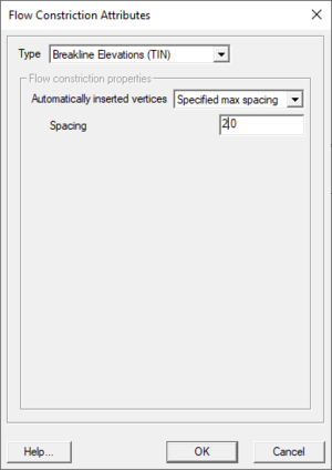
Arcs on the perimeter or within a polygon flow constriction can be used to spatially distribute the properties above. To use an arc for elevations, specify it to be the "Breakline Elevations" type in the arc properties dialog. Elevations can be specified at nodes at the end of arcs but not on intermediate vertices. Therefore, in order to represent curved flow constrictions or changes in slope, it's necessary to convert vertices to nodes to create multiple arc segments. These arcs will become breaklines in the TIN generated by TUFLOW. Points within a polygon can also be used to specify elevations and will become an individual point in the generated TIN.
It is important to keep in mind when using flow constrictions that elevation data comes from a combination of the cell elevations, elevations specified with the flow constriction itself, and elevations assigned to perimeter nodes or interior points depending upon the whether each kind of data exists and the options chosen for the flow constriction.
Creating Flow Constrictions
To create a flow constriction for an arc or polygon:
- Create a 2D Flow Constriction Shapes coverage and an arc/polygon in the coverage. Note that the old 2D Flow Constriction coverage is also still available, and is different from the one being created.
- Double-click on the arc/polygon and change the type to Flow Constriction or Layered Flow Constriction and set the options according to the guidelines below.
Flow Constriction Options
- Width –
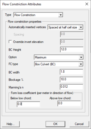
- Override Invert Elevation – Unless overriden, TUFLOW will use the 2D cell elevations for the invert elevations of the flow constriction.
- Option – This controls when invert elevations will be applied. If the choice is Minimum, the new invert elevations will be used only if they are lower than the original cell elevations. Similarly, if the choice is Maximum the new elevations will only be used if they are higher than the original cell elevations. If All is chosen, the new elevations will be used regardless if the elevations are higher or lower.
TUFLOW has the option to merge elevations at the perimeter of the flow constriction with the existing elevations that exist in the perimeter cells to make the transition between the elevations smooth. The Default option (polygons only) will merge elevations of perimeter points that do not have a specified elevation value but apply specified elevations at points. The All option (arcs only) will ignore specified elevations at perimeter points and merge the values with the perimeter points. The No Merge option will ignore existing cell elevations and the elevations will come from specified node values if they exist otherwise they will come from the elevations specified for the flow constriction.
Breakline Elevations
- Automatically Inserted Vertices – Used to affect how TUFLOW generates the TIN to use to interpolate elevation data within the flow constriction. Additional vertices can be useful to provide a better triangulation and more smooth transitions between values. The default is for TUFLOW to generate additional vertices so that the final spacing is not more than half the cell size.
Layered Flow Constriction Options
- Invert Elevation Offset – This will offset the invert elevations whether they are specified or are the original cell elevations.
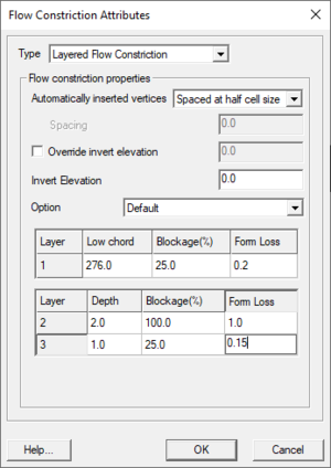
- Layer 1 Low chord – The low chord (obvert) represents the top of layer 1. For a bridge this is the low chord of the bridge deck.
- Layer 2 and 3 Depths – This represent the depth of the layers after layer 1. The obvert of each layer is determined on a cell by cell level from the layer1 low chord/obvert elevation.
- Blockage % – This represents the percentage of the flow width lost due to large piers, railings, or other flow impediments. If half of the flow is blocked, the percentage lost is 50%.
- Form Loss – The form loss is the ratio of the dynamic head that is lost in the structure. This value can be larger than 1.0 since all of the energy does not have to come from the velocity component. This can be estimated from experience or by comparing with other numeric codes.
Non-Layered Flow Constriction Options
- FC Type – Flow constriction Type. Options are:
- "General" – Does not include allowances for any vertical walls or friction from underside of deck.
- "BC" – Box culvert
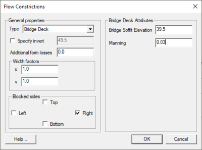
- "BD" – Bridge deck
- "FD" – Floating deck
- Low chord (obvert)/BC Height/Bridge Deck Depth – The usage of this field changes depending on FC Type (above). Enter a sufficiently high value (eg. 99999) if there is no obvert constriction.
- "General" or "BD" – Low chord/Obvert (soffit) of constriction in m above datum.
- "BC" – The height of the box culvert.
- "FD" – Floating depth (m) of the deck (ie. depth below the water line).
- BC Width – The width of one BC culvert barrel in metres. For example, if there are 10 by 1.8m wide culverts, enter a value of 1.8.
- Blockage % – The percentage blockage of the cells. For example, if 40 is entered (ie. 40%), the cell sides are reduced in flow width by 40%, ie. is set to 0.6 times the full flow width.
- Manning's n – According to TUFLOW's documentation:
For box culverts (BC), the Manning’s n of the culverts (typically 0.011 to 0.015) should be specified. This value prevails over any other bed resistance values irrespective of where in the *.tgc file they occur (the exception is if another FC BC object overrides this one). If set to less than 0.001, a default value of 0.013 is used.
For bridge decks (BD), can be used to introduce additional flow resistance once the upstream water level reaches the bridge deck low chord/obvert (or soffit). For floating decks (FD) this is always the case as the deck soffit is permanently submerged. The additional flow resistance is modelled as an increase in bed resistance by increasing the wetted perimeter at the cell mid-side by a factor equal to (2.*Bed_n)/FC_n. For example, if the FC Manning’s n and the bed Manning’s n values are the same, the wetted perimeter is doubled, thereby reducing the conveyance and increasing the resistance to flow. To be used as a calibration parameter to fine-tune the energy losses across a bridge or floating structure.
- Ignored for General FC types.
- Form Loss Coefficient – Form loss coefficient to be applied above and below the FC low chord/obvert. Used for modeling fine-scale “micro” contraction/expansion losses not picked up by the change in the 2D domain’s velocity patterns (eg. bridge pier losses, vena-contracta losses, 3rd (vertical) dimension etc). The effect of these fields changes between arcs and polygons, thick and thin lines, as detailed in the TUFLOW docs (section 4.7.2).
Node Options
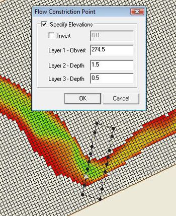
All nodes have the option of overriding the invert height at their location. Beyond this, the fields available in the node attributes dialog change based on whether the node is inside (or on the edge) of a layered flow constriction polygon. If so, the node properties will resemble that of the layered polygon's with layers 1–3. Otherwise only the Low chord (obvert) can be modified.
As with polygons, the low chord can actually mean different things depending on the settings of FC Type and other factors. This is determined by the polygon the node is on or inside of.
Example: Arched Bridge
Because it's hard to glean applicable knowledge from a dry description of dialogs, here's an example of how they might be used. To create an arched bridge using a flow constriction polygon and breakline elevations, do the following:
- Start by creating the flow constriction shapes coverage.
- Next create four connected arcs in a rectangle for the polygon for the bridge. Go to Feature Objects | Build polygons to create the polygon.
- Select the polygon with the Select Feature Polygon tool and double-click enter its attributes dialog.
- Click the Select Feature Arc tool and select both arcs along the sides of the bridge. Turn both these arcs into breakline elevations. Right-click and select Attributes....
- Set the Type to "Breakline Elevations (TIN)".
- Set Automatically insert vertices to "Spaced at half cell size".
- Next create some nodes along these arcs to set different low chord elevations at each one to create the arch. With the arcs still selected, right-click and select Redistribute Vertices.... In the dialog, choose Number of Segments for the Specify field and enter 9 as the number of segments. Click OK. This splits up the lines so that there are a total of 8 vertices on each, which will be converted to nodes.
- Choose the Select Feature Vertex option and select all the vertices on the bridge sides (either with a drag-select or by holding shift). Right-click and choose Convert to Nodes.
- Now it's time to set the node data. Choose the Select Feature Point tool. For each node along the sides of the bridge, enter its attributes dialog (right-click with it selected and choose Node Attributes...) and insert the data below. Multi-select nodes with the SHIFT key and edit their attributes simultaneously. Since both sides of the bridge will be the same, and the data below is symmetrical on each end of the bridge, select 4 nodes at once to set their values to save time.
| Node | L1 Low chord | L2 Depth | L3 Depth |
|---|---|---|---|
| Node1 | 271 | 3 | 0.5 |
| Node2 | 273 | 2 | 0.5 |
| Node3 | 274.5 | 1.5 | 0.5 |
| Node4 | 275.5 | 1.25 | 0.5 |
| Node5 | 276 | 1 | 0.5 |
| Node6 | 276 | 1 | 0.5 |
| Node7 | 275.5 | 1.25 | 0.5 |
| Node8 | 274.5 | 1.5 | 0.5 |
| Node9 | 273 | 2 | 0.5 |
| Node10 | 271 | 3 | 0.5 |
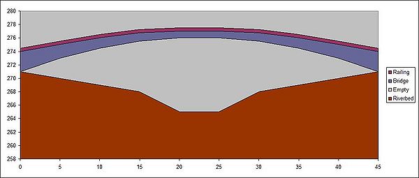
There is now an arched bridge that will look something like the image below from the side. There is an added 25% blockage under the bridge to cover things like pillars holding the bridge up, vegetation, fairy-tale trolls hiding underneath, and so on. Layer 2 is the bridge itself, which provides 100% blockage because the bridge is solid concrete and does not allow any water to flow through that section. Above that, the railing gives 25% blockage but otherwise lets water through just fine. And above that? Nothing—any water that rises above the railing of the bridge is completely unrestricted.
The varying width of Layer 2 allows creating a bridge that is thickest on the ends of the bridge and thin in the center. The Layer 1 blockage takes support pillars into account, and TUFLOW will automatically determine how much of layers 1, 2 and 3 are affecting the water at any given time and calculate the flow constriction from there.
Related Topics
SMS – Surface-water Modeling System | ||
|---|---|---|
| Modules: | 1D Grid • Cartesian Grid • Curvilinear Grid • GIS • Map • Mesh • Particle • Quadtree • Raster • Scatter • UGrid |  |
| General Models: | 3D Structure • FVCOM • Generic • PTM | |
| Coastal Models: | ADCIRC • BOUSS-2D • CGWAVE • CMS-Flow • CMS-Wave • GenCade • STWAVE • WAM | |
| Riverine/Estuarine Models: | AdH • HEC-RAS • HYDRO AS-2D • RMA2 • RMA4 • SRH-2D • TUFLOW • TUFLOW FV | |
| Aquaveo • SMS Tutorials • SMS Workflows | ||
