GMS:Creating a 3D Mesh: Difference between revisions
From XMS Wiki
Jump to navigationJump to search
No edit summary |
|||
| Line 25: | Line 25: | ||
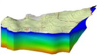
Before constructing a zone of elements, a 2D mesh must be created or imported using the 2D Mesh Module. A pair of TINs must also be created which represent the top and the bottom of the zone. These TINs are typically constructed from borehole data or from scatter points. The zone is then created by selecting the two TINs and selecting the '''Fill Between TINs → 3D Mesh''' command in the ''TINs'' menu. At this point, the user is prompted to enter the number of layers of elements to be created between the TINs and the material that will be associated with the elements in the zone. Each of the elements in the 2D mesh is then "projected" through the two TINs to create a vertical column of 3D elements as shown below. For example, if N layers are specified, N 3D wedge elements are created from each of the triangular elements in the 2D mesh, and N 3D hexahedral elements are created from each of the quadrilateral elements in the 2D mesh. The Z coordinates of the nodes created for the 3D elements are distributed uniformly between the top and the bottom TINs. | Before constructing a zone of elements, a 2D mesh must be created or imported using the 2D Mesh Module. A pair of TINs must also be created which represent the top and the bottom of the zone. These TINs are typically constructed from borehole data or from scatter points. The zone is then created by selecting the two TINs and selecting the '''Fill Between TINs → 3D Mesh''' command in the ''TINs'' menu. At this point, the user is prompted to enter the number of layers of elements to be created between the TINs and the material that will be associated with the elements in the zone. Each of the elements in the 2D mesh is then "projected" through the two TINs to create a vertical column of 3D elements as shown below. For example, if N layers are specified, N 3D wedge elements are created from each of the triangular elements in the 2D mesh, and N 3D hexahedral elements are created from each of the quadrilateral elements in the 2D mesh. The Z coordinates of the nodes created for the 3D elements are distributed uniformly between the top and the bottom TINs. | ||
[[Image:Extrusion1. | [[Image:Extrusion1.png|thumb|left|350 px|Projection technique for creating 3D meshes]] | ||
This process is repeated for each of the zones in the mesh. In order for the nodes at the bottom of one zone to match the nodes at the top of another zone, the same TIN should be used at the bottom of the upper zone and at the top of the lower zone. If the vertices of the TIN are edited in any way after one layer is generated but before an adjacent layer is generated, a gap may be introduced between the two zones of 3D elements. | This process is repeated for each of the zones in the mesh. In order for the nodes at the bottom of one zone to match the nodes at the top of another zone, the same TIN should be used at the bottom of the upper zone and at the top of the lower zone. If the vertices of the TIN are edited in any way after one layer is generated but before an adjacent layer is generated, a gap may be introduced between the two zones of 3D elements. | ||

