GMS:Interpolate to MODFLOW Layers: Difference between revisions
No edit summary |
No edit summary |
||
| (19 intermediate revisions by 3 users not shown) | |||
| Line 1: | Line 1: | ||
[[File:Interpolate to MODFLOW Layers.png|thumb|480 px|The ''Interpolate to MODFLOW Layers'' dialog]] | |||
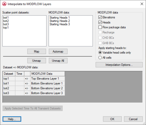
In this dialog | In this dialog, select various 2D scatter point datasets and associate them with MODFLOW input data. GMS will then interpolate from the 2D scatter point data to the MODFLOW input data. | ||
This is often useful to define the layer elevations of a MODFLOW model. See [[GMS:Defining Layer Elevations|Defining Layer Elevations]] for more information on MODFLOW layer elevations. | |||
Associate 2D scatter point data with MODFLOW data by selecting a dataset in the list on the left of the dialog and selecting an item from the MODFLOW data list on the right and then selecting the '''Map''' button. The association between the datasets and the MODFLOW data is shown in the spread sheet labeled ''Dataset → MODFLOW data''. | |||
The ''' | The ''MODFLOW data'' group box contains options to allow picking which MODFLOW data they would like to interpolate to. | ||
*''Elevations'' refers to the top and bottom elevations of the 3D grid. | |||
*''Heads'' refers to the starting heads. | |||
*''Flow package data'' refers to the various input arrays for the LPF or BCF packages (HK, VK...). | |||
*''Recharge'' refers to the recharge rate specified in the RCH package. | |||
*''CHD BCs'' refers to the starting and ending heads associated with existing CHD boundary conditions in the MODFLOW model. | |||
*''GHB BCs'' refers to the starting and ending heads associated with existing GHB boundary conditions in the MODFLOW model. | |||
The Interpolation Options button will bring up the [[GMS:2D_Interpolation_Options|''2D Interpolation Options'' dialog]]. | The '''Automap''' button will try to automatically map the datasets to the MODFLOW data by matching names and layer numbers. The Unmap button is used unmap the selected item(s) in the spread sheet. The '''Unmap All''' button is self explanatory. | ||
The '''Interpolation Options''' button will bring up the [[GMS:2D_Interpolation_Options|''2D Interpolation Options'' dialog]]. | |||
==Transient Interpolation== | ==Transient Interpolation== | ||
If a 2D scatter point | If a 2D scatter point dataset is transient and the user is interpolating to MODFLOW data that does not vary with time then the user will select a time step from that dataset to interpolate to the MODFLOW data. When the user has selected a time step the '''Apply Selected Time To All Transient Datasets''' button will undim. This button allows the user to set the selected time of all of the transient datasets to be the same as the currently selected time. | ||
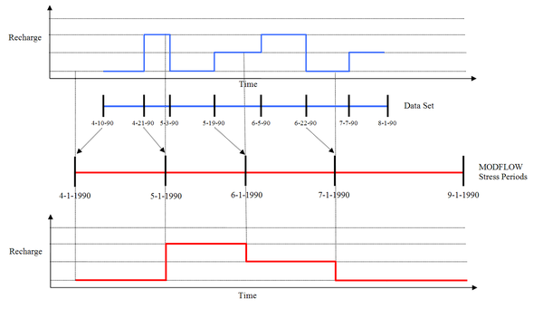
If the current MODFLOW model is transient and the user is interpolating to Recharge then interpolation will occur for each stress period defined in the MODFLOW model. For a particular stress period, the closest data set time step whose time is less than the beginning of the stress period is used. Figure 1 illustrates this process. | If the current MODFLOW model is transient and the user is interpolating to ''Recharge'' then interpolation will occur for each stress period defined in the MODFLOW model. For a particular stress period, the closest data set time step whose time is less than the beginning of the stress period is used. Figure 1 illustrates this process. | ||
{{hide in print|[[File:Rch.PNG|center| | {{hide in print|[[File:Rch.PNG|center|600px|thumb|Figure 1: Transient interpolation of Recharge]]}} | ||
{{only in print|[[File:Rch.PNG|center|450px|thumb|Figure 1: Transient interpolation of Recharge]]}} | {{only in print|[[File:Rch.PNG|center|450px|thumb|Figure 1: Transient interpolation of Recharge]]}} | ||
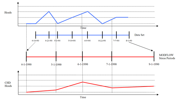
If the current MODFLOW model is transient and the user is interpolating to CHD BCs then interpolation will occur at the beginning and the end of each stress period (because a start head and an end head are specified for each CHD BC). If there is no | If the current MODFLOW model is transient and the user is interpolating to ''CHD BCs'' then interpolation will occur at the beginning and the end of each stress period (because a start head and an end head are specified for each CHD BC). If there is no dataset time step that matches the beginning or the end of the stress period then GMS will linearly interpolate between dataset time steps. Figure 2 illustrates this process. | ||
{{hide in print|[[File:Chd.PNG|center| | {{hide in print|[[File:Chd.PNG|center|600px|thumb|Figure 2: Transient interpolation of CHD BCs]]}} | ||
{{only in print|[[File:Chd.PNG|center|450px|thumb|Figure 2: Transient interpolation of CHD BCs]]}} | {{only in print|[[File:Chd.PNG|center|450px|thumb|Figure 2: Transient interpolation of CHD BCs]]}} | ||
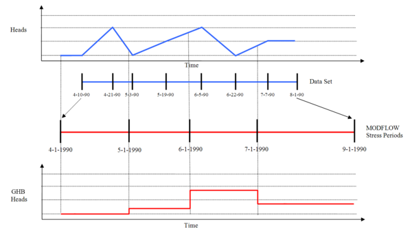
If the current MODFLOW model is transient and the user is interpolating to ''GHB BCs'' then interpolation will occur at the beginning of each stress period. If there is no dataset time step that matches the beginning or the end of the stress period then GMS will linearly interpolate between dataset time steps. Figure 3 illustrates this process. | |||
{{hide in print|[[File:GHB.PNG|center|600px|thumb|Figure 3: Transient interpolation of GHB BCs]]}} | |||
{{only in print|[[File:GHB.PNG|center|450px|thumb|Figure 3: Transient interpolation of GHB BCs]]}} | |||
{{Navbox GMS}} | {{Navbox GMS}} | ||
[[Category:MODFLOW|I]] | |||
Latest revision as of 15:25, 25 August 2017
In this dialog, select various 2D scatter point datasets and associate them with MODFLOW input data. GMS will then interpolate from the 2D scatter point data to the MODFLOW input data.
This is often useful to define the layer elevations of a MODFLOW model. See Defining Layer Elevations for more information on MODFLOW layer elevations.
Associate 2D scatter point data with MODFLOW data by selecting a dataset in the list on the left of the dialog and selecting an item from the MODFLOW data list on the right and then selecting the Map button. The association between the datasets and the MODFLOW data is shown in the spread sheet labeled Dataset → MODFLOW data.
The MODFLOW data group box contains options to allow picking which MODFLOW data they would like to interpolate to.
- Elevations refers to the top and bottom elevations of the 3D grid.
- Heads refers to the starting heads.
- Flow package data refers to the various input arrays for the LPF or BCF packages (HK, VK...).
- Recharge refers to the recharge rate specified in the RCH package.
- CHD BCs refers to the starting and ending heads associated with existing CHD boundary conditions in the MODFLOW model.
- GHB BCs refers to the starting and ending heads associated with existing GHB boundary conditions in the MODFLOW model.
The Automap button will try to automatically map the datasets to the MODFLOW data by matching names and layer numbers. The Unmap button is used unmap the selected item(s) in the spread sheet. The Unmap All button is self explanatory.
The Interpolation Options button will bring up the 2D Interpolation Options dialog.
Transient Interpolation
If a 2D scatter point dataset is transient and the user is interpolating to MODFLOW data that does not vary with time then the user will select a time step from that dataset to interpolate to the MODFLOW data. When the user has selected a time step the Apply Selected Time To All Transient Datasets button will undim. This button allows the user to set the selected time of all of the transient datasets to be the same as the currently selected time.
If the current MODFLOW model is transient and the user is interpolating to Recharge then interpolation will occur for each stress period defined in the MODFLOW model. For a particular stress period, the closest data set time step whose time is less than the beginning of the stress period is used. Figure 1 illustrates this process.
If the current MODFLOW model is transient and the user is interpolating to CHD BCs then interpolation will occur at the beginning and the end of each stress period (because a start head and an end head are specified for each CHD BC). If there is no dataset time step that matches the beginning or the end of the stress period then GMS will linearly interpolate between dataset time steps. Figure 2 illustrates this process.
If the current MODFLOW model is transient and the user is interpolating to GHB BCs then interpolation will occur at the beginning of each stress period. If there is no dataset time step that matches the beginning or the end of the stress period then GMS will linearly interpolate between dataset time steps. Figure 3 illustrates this process.
| [hide] GMS – Groundwater Modeling System | ||
|---|---|---|
| Modules: | 2D Grid • 2D Mesh • 2D Scatter Point • 3D Grid • 3D Mesh • 3D Scatter Point • Boreholes • GIS • Map • Solid • TINs • UGrids | |
| Models: | FEFLOW • FEMWATER • HydroGeoSphere • MODAEM • MODFLOW • MODPATH • mod-PATH3DU • MT3DMS • MT3D-USGS • PEST • PHT3D • RT3D • SEAM3D • SEAWAT • SEEP2D • T-PROGS • ZONEBUDGET | |
| Aquaveo | ||


