GMS:Basic Transport Package Dialog: Difference between revisions
From XMS Wiki
Jump to navigationJump to search
(→Units) |
|||
| (14 intermediate revisions by 3 users not shown) | |||
| Line 1: | Line 1: | ||
[[File:MT3D-transport.jpg|thumb|360 px|The | {{MT3DMS Links}} | ||
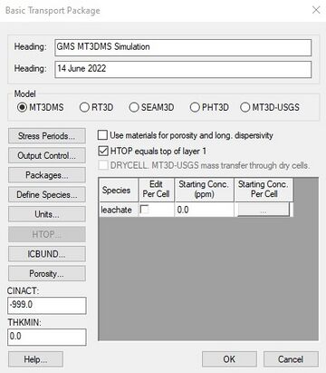
The first step in setting up an [[GMS:MT3DMS|MT3DMS]] simulation is to define the data for the Basic Transport | [[File:MT3D-transport.jpg|thumb|360 px|The MT3D3D ''Basic Transport Package'' dialog.]] | ||
The first step in setting up an [[GMS:MT3DMS|MT3DMS]] simulation is to define the data for the ''Basic Transport Package''. The information defined in the ''Basic Transport Package'' includes the computational time intervals (stress periods), an array defining which cells are inactive and which cells have constant concentration, an array defining aquifer porosity, and array of starting concentration values. The input data for the ''Basic Transport Package'' must be entered before editing any of the other packages in the MT3DMS simulation. | |||
The ''Basic Transport Package'' dialog contains the following options: | |||
===Headings=== | ===Headings=== | ||
| Line 6: | Line 9: | ||
===Model Selection=== | ===Model Selection=== | ||
The Model section in the middle of the ''Basic Transport Package'' dialog is used to select which transport model is to be used. The menu commands and packages and options that are available depend on which model is selected. All MT3DMS-based transport models are contained in the ''MT3DMS'' menu. See the [[GMS:RT3D|RT3D]], [[GMS:SEAM3D|SEAM3D]] | The Model section in the middle of the ''Basic Transport Package'' dialog is used to select which transport model is to be used. The menu commands and packages and options that are available depend on which model is selected. All MT3DMS-based transport models are contained in the ''MT3DMS'' menu. See the [[GMS:RT3D|RT3D]], [[GMS:SEAM3D|SEAM3D]], [[GMS:PHT3D|PHT3D]], and [[GMS:MT3D-USGS|MT3D-USGS]] pages for more information on those transport models. | ||
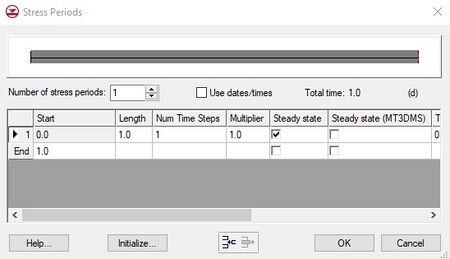
[[File:MT3D-StressPeriods.jpg|thumb|450 px|The MT3DMS ' | [[File:MT3D-StressPeriods.jpg|thumb|450 px|The MT3DMS ''Stress Periods'' dialog.]] | ||
===Stress Periods=== | ===Stress Periods=== | ||
| Line 18: | Line 21: | ||
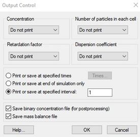
[[File:MT3D-OC.jpg|thumb|275 px|The MT3DMS ''Output Control'' dialog.]] | [[File:MT3D-OC.jpg|thumb|275 px|The MT3DMS ''Output Control'' dialog.]] | ||
Options for printing and saving the results from an MT3DMS simulation are also included in the Basic Transport | Options for printing and saving the results from an MT3DMS simulation are also included in the ''Basic Transport Package''. The MT3DMS output control options are modified by selecting the '''Output Control''' button on the left side of the ''Basic Transport Package'' dialog. This brings up the ''MT3D Output Control'' dialog. | ||
One of the output options is an unformatted (binary) concentration file which is used for post-processing by GMS. This option is selected using the toggle at the bottom of the dialog. With the version of MT3DMS included with GMS, the concentration file is saved directly from MT3DMS as a GMS binary scalar dataset file. | One of the output options is an unformatted (binary) concentration file which is used for post-processing by GMS. This option is selected using the toggle at the bottom of the dialog. With the version of MT3DMS included with GMS, the concentration file is saved directly from MT3DMS as a GMS binary scalar dataset file. | ||
Another option is to ''Print or save at specified times''. When this option is selected, the '''Times''' button is undimmed. Selecting the '''Times''' button brings up a spreadsheet that enables specifying the times that the output will be printed or saved. The spreadsheet can be quickly initialized by selecting the '''Initialize Values''' button at the bottom of the dialog. This button brings up the ''Initialize Time Steps'' dialog. This dialog is composed of edit fields that will automatically populate the times that | Another option is to ''Print or save at specified times''. When this option is selected, the '''Times''' button is undimmed. Selecting the '''Times''' button brings up a spreadsheet that enables specifying the times that the output will be printed or saved. The spreadsheet can be quickly initialized by selecting the '''Initialize Values''' button at the bottom of the dialog. This button brings up the ''Initialize Time Steps'' dialog. This dialog is composed of edit fields that will automatically populate the times that MT3DMS data will be saved or printed. | ||
===Packages=== | ===Packages=== | ||
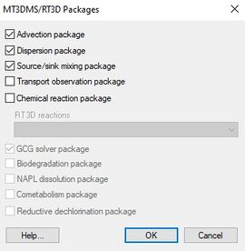
The '''Packages''' button on the left of the ''Basic Transport Package'' dialog brings up the ''Packages'' dialog. This dialog is used to specify which of the packages are to be used in the simulation. The check box to the left of the package name is selected to signify that a package will be utilized as part of the simulation. Some of the packages are used by RT3D or SEAM3D and are dimmed for MT3DMS simulations. | The '''Packages''' button on the left of the ''Basic Transport Package'' dialog brings up the ''Packages'' dialog. This dialog is used to specify which of the [[GMS:MT3DMS Packages|packages]] are to be used in the simulation. The check box to the left of the package name is selected to signify that a package will be utilized as part of the simulation. Some of the packages are used by RT3D or SEAM3D and are dimmed for MT3DMS simulations. | ||
[[File:MT3D-RT3D-Packages.jpg|thumb|none|center|270 px|The ''MT3DMS/RT3D Packages'' dialog.]] | [[File:MT3D-RT3D-Packages.jpg|thumb|none|center|270 px|The ''MT3DMS/RT3D Packages'' dialog.]] | ||
| Line 52: | Line 55: | ||
Another option would be to use the default approach and lower the value of the layer 1 top elevation array. For unconfined layers, this array is not used by MODFLOW anyway. The only reason to keep the HTOP array separate from the top elevation array is for visualization. When a MODFLOW solution is displayed in side view, GMS plots the computed water table on top of the cross section display. Using the top elevation of layer 1 as the ground surface makes it possible to see exactly where the water table lies in relation to the ground surface and illustrates where cells are flooded. | Another option would be to use the default approach and lower the value of the layer 1 top elevation array. For unconfined layers, this array is not used by MODFLOW anyway. The only reason to keep the HTOP array separate from the top elevation array is for visualization. When a MODFLOW solution is displayed in side view, GMS plots the computed water table on top of the cross section display. Using the top elevation of layer 1 as the ground surface makes it possible to see exactly where the water table lies in relation to the ground surface and illustrates where cells are flooded. | ||
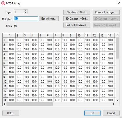
[[File:MT3D-HTOP.jpg|thumb|420 px|The | [[File:MT3D-HTOP.jpg|thumb|420 px|The MT3DMS ''HTOP Array'' dialog.]] | ||
===DRYCELL=== | |||
The DRYCELL check box enables mass transfer through dry cells from [[GMS:MODFLOW-NWT|MODFLOW-NWT]] models. This feature is available in [[GMS:MT3D-USGS|MT3D-USGS]]. | |||
===HTOP and Thickness Arrays=== | ===HTOP and Thickness Arrays=== | ||
| Line 66: | Line 72: | ||
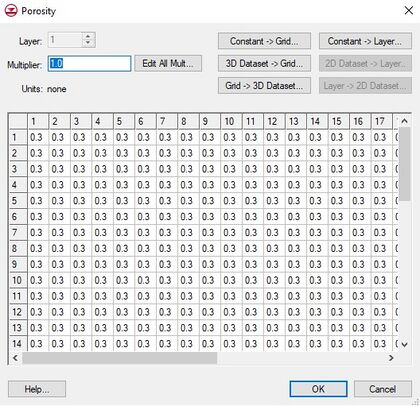
The array defining the porosity of each cell in the model can be defined and edited by selecting the '''Porosity''' button in the ''Basic Transport Package''. This array can also be initialized using a conceptual model in the Map module. It can also be edited on a cell-by-cell basis using the [[GMS:Cell Properties|'''Cell Properties''']] command. | The array defining the porosity of each cell in the model can be defined and edited by selecting the '''Porosity''' button in the ''Basic Transport Package''. This array can also be initialized using a conceptual model in the Map module. It can also be edited on a cell-by-cell basis using the [[GMS:Cell Properties|'''Cell Properties''']] command. | ||
[[File:MT3D-Porisity.jpg|thumb|none|center|420 px|The | [[File:MT3D-Porisity.jpg|thumb|none|center|420 px|The MT3DMS ''Porosity'' dialog.]] | ||
