SMS:FESWMS Model Control Dialog: Difference between revisions
From XMS Wiki
Jump to navigationJump to search
No edit summary |
|||
| (21 intermediate revisions by the same user not shown) | |||
| Line 1: | Line 1: | ||
The ''FESWMS | __NOINDEX__ | ||
{{SMS Deprecated Feature}} | |||
The ''FESWMS Model Control'' dialog is used to set general simulation options. This document highlights the more commonly used options. Refer to the FESWMS manual[http://www.cflhd.gov/design/hyd/flo2dh_manual3.pdf] for a more detailed description of how these parameters affect the model results. | |||
== General Tab == | == General Tab == | ||
| Line 6: | Line 8: | ||
*Network stamp and BC descriptor | *Network stamp and BC descriptor | ||
::These are comments that are added at the top of the FESWMS input files. The network file (*.net) includes only the network stamp but the bc file includes both the network stamp and the bc descriptor. | |||
*Slip conditions | *Slip conditions | ||
::This controls how boundaries are handled by FESWMS. Slip boundaries allows water to move freely along the boundary. No slip fixes the velocity at fixed boundaries to 0.0. Semi-slip allows water to move along boundaries but reduces the velocities. | |||
*Run Type | *Run Type | ||
::A simulation can compute hydrodynamics, sediment, or both hydrodynamics and sediment (semi-coupled). It is not recommended to use the sediment only option. Use the semi-coupled option instead. | |||
*Solution Type | *Solution Type | ||
::This controls whether the simulation will be treated as steady state or dynamic (time dependent). A steady state run requires boundary conditions that do not change and computes a solution that does not change through time. | |||
*Input Options | *Input Options | ||
::This controls the files that will be used in FESWMS. | |||
::An INI (initial conditions) file is used to provide an initial solution for FESWMS. The initial conditions file format is identical to the FESWMS solution file format and a FESWMS solution may be used for an initial conditions file. Initial conditions files can also be created from inside of SMS. INI files are used as hot starts in the spin down process. | |||
*Output Options | *Output Options | ||
::The scalar dataset file and vector dataset files are additional output files written in the EMRL dataset format. Regardless of whether this file is used or not, the datasets water surface elevation, depth, and velocities are written to the *.flo solution file. The dataset files will have the same base name as the other project files and have the extensions *.scl (scalar) and *.vec (vector). The data written to the dataset file can be specified by clicking on the options button. Available scalar datasets include: Depth-averaged velocity magnitude, Unit flow rate magnitude, Froude number, Mechanical energy head elevation, Bed shear stress magnitude, Vorticity magnitude, Wind Speed, Depth of general scour, Scoured bed elevation, Sediment concentration, Sediment volumetric transport rate, Sediment volumetric transport capacity, and Sediment transport rate deficit. Available vector datasets include: Depth-averaged flow velocities, Unit flow rate, Bed shear stress, Tropical cyclone wind velocities, Sediment volumetric transport rates, and Sediment volumetric transport capacities. | |||
== Timing Tab == | == Timing Tab == | ||
[[Image:FESWMS MC Timing.jpg|thumb|450 px|''FESWMS Model Control'' dialog showing the ''Timing'' tab]] | [[Image:FESWMS MC Timing.jpg|thumb|450 px|''FESWMS Model Control'' dialog showing the ''Timing'' tab]] | ||
* Relaxation factor | * Relaxation factor | ||
::Affects how fast and reliable FESWMS will find a solution. Reducing this value may help FESWMS achieve a solution but may increase runtime. | |||
* Iterations | * Iterations | ||
::This is the maximum number of iterations to perform. There will be fewer iterations if the model reaches the convergence parameters before reaching this number of iterations (see parameters tab for convergence parameters). | |||
* Starting time | * Starting time | ||
::The time to start a dynamic simulation in hours. | |||
* Run time | * Run time | ||
::The length of the simulation in hours. | |||
* Time step size | * Time step size | ||
::The length of time for each time step in hours. FESWMS is an implicit model so the time step size is not dependent upon the courant number. | |||
== Parameters Tab == | == Parameters Tab == | ||
[[Image:FESWMS MC Parameters.jpg|thumb|450 px|''FESWMS Model Control'' dialog showing the ''Parameters'' tab]] | [[Image:FESWMS MC Parameters.jpg|thumb|450 px|''FESWMS Model Control'' dialog showing the ''Parameters'' tab]] | ||
* General Parameters | * General Parameters | ||
** Water surface elevation | |||
* Water surface elevation | **:This is the initial water surface elevation for a cold start simulation. This number should always be larger than the elevation of the highest node in the mesh. | ||
** Unit flow convergence | |||
* Unit flow convergence | **:The maximum change of unit flow between iterations that will be considered a acceptable for a converged solution. | ||
** Water depth convergence | |||
* Water depth convergence | **:The maximum change of water depth between iterations that will be considered acceptable for a converged solution. | ||
** Storativity depth | |||
* Storativity depth | **:Storativity allows an element to remain active as long as the water surface elevation is above the highest node value minus the storativity depth. Specifying a non-zero storativity value generally increases the stability of the model. | ||
** Element wetting/drying | |||
* Element wetting/drying | **:Unless this is checked, FESWMS will not allow elements to wet and dry during a simulation. | ||
** Depth tolerance for drying | |||
* Depth tolerance for drying | **:Indicates the required depth to re-wet a dry node. If this value is zero, any depth above the node will re-wet a dry element. Using a value greater than zero helps prevent wet/dry excessive wet/dry oscillations that can lead to instabilities. | ||
*Reference Point Location | *Reference Point Location | ||
** Latitude | |||
* Latitude | ** Longitude | ||
* Longitude | ** Angle | ||
* Angle | ** X-Coordinate | ||
* X-Coordinate | ** Y-Coordinate | ||
* Y-Coordinate | |||
*Default Weir Paremeters | *Default Weir Paremeters | ||
** Default tailwater | |||
* Default tailwater | ** Default minimum head | ||
* Default minimum head | |||
*Default Culvert Parameters | *Default Culvert Parameters | ||
** Tailwater elevation | |||
* Tailwater elevation | ** Minimum head difference | ||
* Minimum head difference | |||
*Default Channel Link Parameters | *Default Channel Link Parameters | ||
** Tailwater elevation | |||
* Tailwater elevation | ** Minimum head difference | ||
* Minimum head difference | |||
*Default Gate Parameters | *Default Gate Parameters | ||
** Tailwater elevation | |||
* Tailwater elevation | ** Minimum head difference | ||
* Minimum head difference | |||
* FST2DH Task | * FST2DH Task | ||
** Check Network | |||
* Check Network | ** Resequence | ||
* Resequence | |||
== Print Tab == | == Print Tab == | ||
| Line 92: | Line 80: | ||
This tab controls the information that is written to the printed output file (*.prt). | This tab controls the information that is written to the printed output file (*.prt). | ||
*Extras | *Extras | ||
**Wide column format | |||
*Wide column format | **ECHO to screen | ||
*ECHO to screen | **Sound beeps after run | ||
*Sound beeps after run | ***Number beeps | ||
*Number beeps | |||
*Output Print | *Output Print | ||
**ECHO input | |||
*ECHO input | **Elements and nodes | ||
*Elements and nodes | **Initial conditions | ||
*Initial conditions | **Element assembly sequence | ||
*Element assembly sequence | **DOF array | ||
*DOF array | **Nodal scalar data | ||
*Nodal scalar data | **Nodal vector data | ||
*Nodal vector data | **Pier scour data | ||
*Pier scour data | **Clear water scour | ||
*Clear water scour | **Include nodal unit flow rates | ||
*Include nodal unit flow rates | |||
*Iteration Print Code | *Iteration Print Code | ||
**Print diagnostics every: | |||
*Print diagnostics every: | |||
*Reports | *Reports | ||
**Weirs | |||
*Weirs | **Drop Inlets | ||
*Drop Inlets | **Piers | ||
*Piers | **Links | ||
*Links | **Culverts | ||
*Culverts | |||
== Sediment Transport == | == Sediment Transport == | ||
| Line 131: | Line 109: | ||
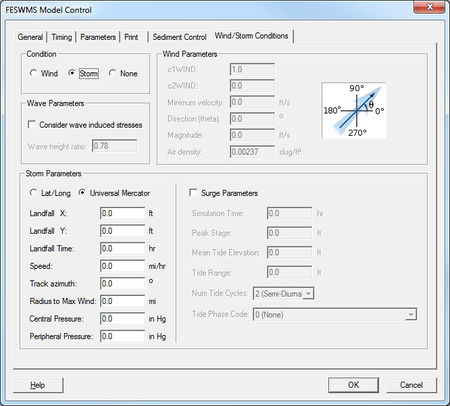
== Wind/Storm Conditions Tab == | == Wind/Storm Conditions Tab == | ||
* Condition | * Condition | ||
::Wind conditions include none, a directional wind, or a storm (cyclone or hurricane). | |||
* Wind Parameters | * Wind Parameters | ||
::These parameters are used to define the parameters for a directional wind (the same direction magnitude for the entire model domain). | |||
* Storm Parameters | * Storm Parameters | ||
::These parameters are used to define a hurricane or cyclone moving across the model domain. The storm parameters such as direction and central pressure are constant throughout the simulation. The effect of a storm surge combined with the wind fields can be defined using the surge parameters toggle. See the FESWMS manual for a description of the input parameters. | |||
* Wave Parameters | * Wave Parameters | ||
::FESWMS has the ability to consider wave induced stresses. The wave height ratio is the breaking water wave height to depth ratio. Waves will break when the significant wave height equals the water depth times this ratio. | |||
[[Image:FESWMS MC Wind.jpg|thumb|none|left|450 px|''FESWMS Model Control'' showing the ''Wind/Storm Conditions'' tab]] | [[Image:FESWMS MC Wind.jpg|thumb|none|left|450 px|''FESWMS Model Control'' showing the ''Wind/Storm Conditions'' tab]] | ||
| Line 151: | Line 129: | ||
[[Category:FESWMS|Model Control Dialog]] | [[Category:FESWMS|Model Control Dialog]] | ||
[[Category:SMS | [[Category:FESWMS Dialogs|Mod]] | ||
[[Category:SMS Model Control|F]] | |||
[[Category:External Links]] | |||
[[Category:Archived]] | |||
Latest revision as of 14:20, 10 June 2019
| This contains information about features no longer in use for the current release of SMS. The content may not apply to current versions. |
The FESWMS Model Control dialog is used to set general simulation options. This document highlights the more commonly used options. Refer to the FESWMS manual[1] for a more detailed description of how these parameters affect the model results.
General Tab
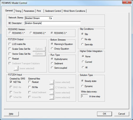
The controls in the General tab include model description, FESWMS version, run controls, input options, and output options.
- Network stamp and BC descriptor
- These are comments that are added at the top of the FESWMS input files. The network file (*.net) includes only the network stamp but the bc file includes both the network stamp and the bc descriptor.
- Slip conditions
- This controls how boundaries are handled by FESWMS. Slip boundaries allows water to move freely along the boundary. No slip fixes the velocity at fixed boundaries to 0.0. Semi-slip allows water to move along boundaries but reduces the velocities.
- Run Type
- A simulation can compute hydrodynamics, sediment, or both hydrodynamics and sediment (semi-coupled). It is not recommended to use the sediment only option. Use the semi-coupled option instead.
- Solution Type
- This controls whether the simulation will be treated as steady state or dynamic (time dependent). A steady state run requires boundary conditions that do not change and computes a solution that does not change through time.
- Input Options
- This controls the files that will be used in FESWMS.
- An INI (initial conditions) file is used to provide an initial solution for FESWMS. The initial conditions file format is identical to the FESWMS solution file format and a FESWMS solution may be used for an initial conditions file. Initial conditions files can also be created from inside of SMS. INI files are used as hot starts in the spin down process.
- Output Options
- The scalar dataset file and vector dataset files are additional output files written in the EMRL dataset format. Regardless of whether this file is used or not, the datasets water surface elevation, depth, and velocities are written to the *.flo solution file. The dataset files will have the same base name as the other project files and have the extensions *.scl (scalar) and *.vec (vector). The data written to the dataset file can be specified by clicking on the options button. Available scalar datasets include: Depth-averaged velocity magnitude, Unit flow rate magnitude, Froude number, Mechanical energy head elevation, Bed shear stress magnitude, Vorticity magnitude, Wind Speed, Depth of general scour, Scoured bed elevation, Sediment concentration, Sediment volumetric transport rate, Sediment volumetric transport capacity, and Sediment transport rate deficit. Available vector datasets include: Depth-averaged flow velocities, Unit flow rate, Bed shear stress, Tropical cyclone wind velocities, Sediment volumetric transport rates, and Sediment volumetric transport capacities.
Timing Tab
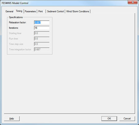
- Relaxation factor
- Affects how fast and reliable FESWMS will find a solution. Reducing this value may help FESWMS achieve a solution but may increase runtime.
- Iterations
- This is the maximum number of iterations to perform. There will be fewer iterations if the model reaches the convergence parameters before reaching this number of iterations (see parameters tab for convergence parameters).
- Starting time
- The time to start a dynamic simulation in hours.
- Run time
- The length of the simulation in hours.
- Time step size
- The length of time for each time step in hours. FESWMS is an implicit model so the time step size is not dependent upon the courant number.
Parameters Tab
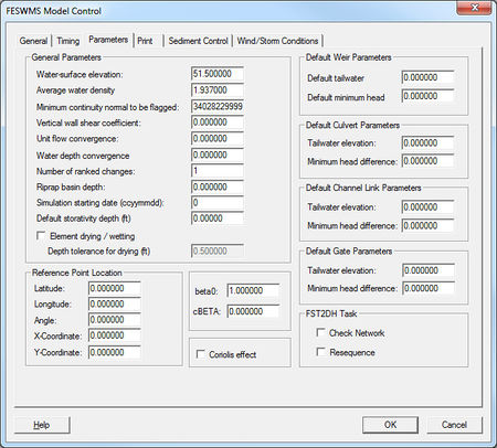
- General Parameters
- Water surface elevation
- This is the initial water surface elevation for a cold start simulation. This number should always be larger than the elevation of the highest node in the mesh.
- Unit flow convergence
- The maximum change of unit flow between iterations that will be considered a acceptable for a converged solution.
- Water depth convergence
- The maximum change of water depth between iterations that will be considered acceptable for a converged solution.
- Storativity depth
- Storativity allows an element to remain active as long as the water surface elevation is above the highest node value minus the storativity depth. Specifying a non-zero storativity value generally increases the stability of the model.
- Element wetting/drying
- Unless this is checked, FESWMS will not allow elements to wet and dry during a simulation.
- Depth tolerance for drying
- Indicates the required depth to re-wet a dry node. If this value is zero, any depth above the node will re-wet a dry element. Using a value greater than zero helps prevent wet/dry excessive wet/dry oscillations that can lead to instabilities.
- Water surface elevation
- Reference Point Location
- Latitude
- Longitude
- Angle
- X-Coordinate
- Y-Coordinate
- Default Weir Paremeters
- Default tailwater
- Default minimum head
- Default Culvert Parameters
- Tailwater elevation
- Minimum head difference
- Default Channel Link Parameters
- Tailwater elevation
- Minimum head difference
- Default Gate Parameters
- Tailwater elevation
- Minimum head difference
- FST2DH Task
- Check Network
- Resequence
Print Tab
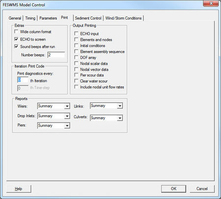
This tab controls the information that is written to the printed output file (*.prt).
- Extras
- Wide column format
- ECHO to screen
- Sound beeps after run
- Number beeps
- Output Print
- ECHO input
- Elements and nodes
- Initial conditions
- Element assembly sequence
- DOF array
- Nodal scalar data
- Nodal vector data
- Pier scour data
- Clear water scour
- Include nodal unit flow rates
- Iteration Print Code
- Print diagnostics every:
- Reports
- Weirs
- Drop Inlets
- Piers
- Links
- Culverts
Sediment Transport
This tab defines the parameters used for sediment transport including bed configuration. See FESWMS Sediment Control for more information.
Wind/Storm Conditions Tab
- Condition
- Wind conditions include none, a directional wind, or a storm (cyclone or hurricane).
- Wind Parameters
- These parameters are used to define the parameters for a directional wind (the same direction magnitude for the entire model domain).
- Storm Parameters
- These parameters are used to define a hurricane or cyclone moving across the model domain. The storm parameters such as direction and central pressure are constant throughout the simulation. The effect of a storm surge combined with the wind fields can be defined using the surge parameters toggle. See the FESWMS manual for a description of the input parameters.
- Wave Parameters
- FESWMS has the ability to consider wave induced stresses. The wave height ratio is the breaking water wave height to depth ratio. Waves will break when the significant wave height equals the water depth times this ratio.
Related Topics
SMS – Surface-water Modeling System | ||
|---|---|---|
| Modules: | 1D Grid • Cartesian Grid • Curvilinear Grid • GIS • Map • Mesh • Particle • Quadtree • Raster • Scatter • UGrid |  |
| General Models: | 3D Structure • FVCOM • Generic • PTM | |
| Coastal Models: | ADCIRC • BOUSS-2D • CGWAVE • CMS-Flow • CMS-Wave • GenCade • STWAVE • WAM | |
| Riverine/Estuarine Models: | AdH • HEC-RAS • HYDRO AS-2D • RMA2 • RMA4 • SRH-2D • TUFLOW • TUFLOW FV | |
| Aquaveo • SMS Tutorials • SMS Workflows | ||
