SMS:Bridge Scour: Difference between revisions
| Line 68: | Line 68: | ||
**'''View Values''' – Opens a dialog showing the bridge scour values for the selected scenario. See below for more information. | **'''View Values''' – Opens a dialog showing the bridge scour values for the selected scenario. See below for more information. | ||
<!--*''Bridge Deck Width'' – This is optional. Enter the width of the bridge deck. If this is left at 0, then the longer of the two lengths of the abutment toe arc will be used. This is used to roughly estimate the area of influence of the bridge.--> | <!--*''Bridge Deck Width'' – This is optional. Enter the width of the bridge deck. If this is left at 0, then the longer of the two lengths of the abutment toe arc will be used. This is used to roughly estimate the area of influence of the bridge.--> | ||
''BridgeDeck'' | |||
*'''Select''' | |||
''Model Specifications'' – This section has two options needed define how the bridge scour will compute values. | ''Model Specifications'' – This section has two options needed define how the bridge scour will compute values. | ||
*''Contraction Scour Variable Extraction Approach'' – Determines the widths transporting sediment for the contraction scour. | *''Contraction Scour Variable Extraction Approach'' – Determines the widths transporting sediment for the contraction scour. | ||
Revision as of 21:54, 15 June 2021
The Bridge Scour coverage will take an existing dataset from a 2d hydraulic modeling of a bridge crossing or proposed bridge crossing site and export many of the needed the variables to Hydraulic Toolbox for a scour analysis. SRH-2D is the recommended 2D hydraulics model. However, the Bridge Scour coverage only requires a 2D mesh with elevation, water surface elevation, water depth and velocity datasets.
The Bridge Scour coverage requires creating and placing a contracted scour section arc, approach scour section arc, channel centerline arc, channel bank arcs, and abutment toe arcs. The user may supply pier arcs if applicable. When creating arcs, the coverage will automatically cycle through the arc types. See Bridge Scour Arc Attributes below for more information on the order these arcs should be created.
The computations will also require a gradation definition of the main channel sediment.
While Bridge Scour coverage will generate most of the values needed, some parameters will still need to be specified within Hydraulic Toolbox.
Welcome Dialog
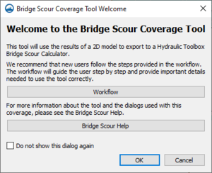
When accessing the Bridge Scour Coverage Properties dialog, the Bridge Scour Coverage Tool Welcome dialog will appear unless it has been turned off. This dialog has the following options:
- Workflow – Opens the wiki article containing the bridge sour workflows.
- Bridge Scour Help – Opens the wiki article for bridge scour.
- Do not show this dialog again – Turning on this option will keep this dialog from appearing when entering the Bridge Scour Coverage Properties dialog. This option can also be turned on or off in the Bridge Scour Default Options dialog.
Bridge Scour Coverage Properties Dialog
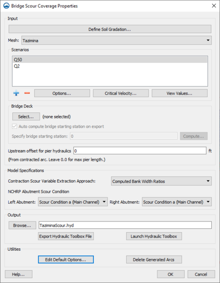
Right-clicking on the Bridge Scour coverage in the Project Explorer and selecting the Custom Properties command will open the Bridge Scour Coverage Properties dialog. The dialog also appears when the Bridge Scour coverage is first created.
The dialog has the following options:
Inputs – This section contains input parameters for the bridge scour computations.
- Define Soil Gradation – Opens the Bridge Scour Soil Gradation dialog. See below for more information.
- Mesh – Defines which 2D mesh will be used. The available datasets for the next options will depend on which 2D mesh is selected.
- Scenarios – Scenarios allow generating multiple bridge scour results using the same data, but varying the parameters.
- Add Scenario
 – Creates a new scenario. Will bring up the Edit Bridge Scour Scenario dialog.
 - Delete Scenario
 – Removes the selected scenario.
 - Options – Opens the Edit Bridge Scour Scenario dialog for the selected scenario. See below for more information.
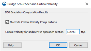
- Critical Velocity – Opens the Bridge Scour Scenario Critical Velocity dialog. See below for more information.
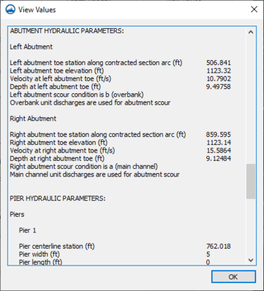
- View Values – Opens a dialog showing the bridge scour values for the selected scenario. See below for more information.
- Add Scenario
BridgeDeck
- Select
Model Specifications – This section has two options needed define how the bridge scour will compute values.
- Contraction Scour Variable Extraction Approach – Determines the widths transporting sediment for the contraction scour.
- "Bank Width Ratios" – Measures the width between the channel bank arcs and determines the flow along this length then passes these values to the Hydraulic Toolbox. This approach is recommended if the flows vary a lot.
- "Computed Bank Width Ratios" – This is similar to the "Bank Width Ratios" option, except that it computes the point of critical velocity (where sediment transport begins to be active) along the approach arc to determine the bank width and flow for the approach arc.
- NCHRP Abutment Scour Condition – Determines whether the left and right abutments are type A or B. The left and right abutments can be individually set to be the same type or can differ depending on the desired result.
- "Type a (Main Channel)"
- "Type b (Overbank)"
Output Filename – A filename for the bridge scour output may be entered here. The file will be saved to the location of the project unless otherwise specified by clicking the Browse button and using the Choose File dialog to select a different location.
Compute Scour Values – The sections has options to preview or export the bridge scour values.
- View Values – Open a dialog displaying all of the computed parameters from the datasets and coverage.
- Export Hydraulic Toolbox File – Runs the bridge scour computations and creates the file.
Advanced – This section allows access to options that are not needed for most simulations, but may be necessary in some cases.
- Edit Advanced Options – Opens the Bridge Scour Advanced Options dialog containing additional parameters.
- Delete Generated Arcs – Removes the arcs generated when exporting the bridge scour file or viewing the bridge scour values.
Bridge Scour Soil Gradation
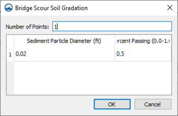
The Bridge Scour Soil Gradation dialog, contains a table for defining the gradation of the main channel. Select how many and which gradations to provide. If providing only one point, D50 is required. If giving multiple points, providing the D50 is recommended.
- Number of Points
- Sediment Particle Diameter
- Percent Passing
Edit Bridge Scour Scenario
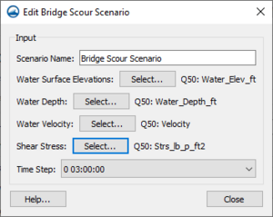
The parameters for each scenario are set in the Edit Bridge Scour Scenario dialog. The parameters are set when first creating the scenario, but can also be define later.
- Scenario Name – Allows entering a name for the scenario. If a solution folder was selected, the name of the solution folder will be used as the default name.
- Water Surface Elevations – Defines which dataset under the selected 2D mesh to use as the water surface elevation.
- Water Depth – Defines which dataset under the selected 2D mesh to use as the depth.
- Water Velocity – Defines which dataset under the selected 2D mesh to use as the velocity.
- Time Step – Allows selecting a particular time step for the solution being used in the scenario.
Critical Velocity
The critical velocity parameters can be set for each scenario.
- Override Critical Velocity Computations
- Critical Velocity for Sediments
View Values
The View Values button will bring up a dialog containing the bridge scour output for the selected scenario. This allows previewing the values before exporting.
Default Options
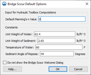
The default options do not need to be changed for most simulations. However, in some cases additional parameters need to be adjusted to increase accuracy. Modifying Manning's n and the constants will update these values throughout the Hydraulic Toolbox file. This may mean modifying the same value several times in Hydraulic Toolbox, but only once in SMS. The following options are available: Input for Hydraulic Toolbox Computations
- Default Manning's n Value
Constants
- Unit Weight of Water
- Unit Weight of Sediment
- Temperature of Water
- Density of Water
- Sediment Angle of Repose
Bridge Scour Arc Attributes
When creating arcs on a Bridge Scour coverage, the arc type is automatically assigned based on the order used to create the arc. The coverage will automatically cycle through the arc types. The first arc created will be a "Contracted Section Arc" followed by an "Approach Section Arc", then the "Centerline Arc". The next four arcs will be two "Bank Arcs", and then two "Abutment Toe Arcs". Once these are all defined, the final arcs will be "Pier arcs".
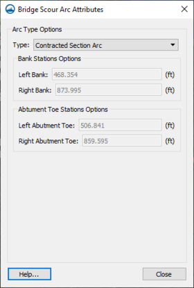
When creating the Bridge Scour coverage from an existing coverage, or using arc from a shapefile, the arcs will be assigned the arc type based on the arc ID order. This will likely require changing the arc types. To manually change, or to view, the arc type, select the arc, right-click, and select the Attributes command to open the Bridge Scour Arc Attributes dialog. The dialog allows setting the arc types as explained below.
Type – Displays the type associated with the arc.
- "Contracted Section Arc" – It is important that the contracted arc be created in the correct direction starting on the left side of the river and crossing to the right side. The centerline, bank, abutment toe and pier arcs can be created in either direction.
- The contracted section arc is created at the maximum contraction of flow through the bridge constriction within the bridge limits. It is not a concern if the maximum contraction occurs downstream of the bridge. For a skewed case, the upstream and downstream limits would incorporate the rectangular footprint based on the upstream and downstream extents. It begins on the left side of the stream (looking downstream), where the projected edge of the stream intersects with the roadway. It travels along the roadway until it reaches the same intersection on the right side. When viewing the feature attributes of this arc, it will provide the stations of the bank arcs and abutment arcs, if they are defined.
- Bank Stations Options – Computed location of the "Bank Arcs" along the "Contracted Section Arc".
- Abutment Toe Stations Options – Location of the "Abutment Toe Arcs" along the "Contracted Section Arc".
- "Approach Arc" – The approach section arc will span the entire width of flow and travel perpendicular to the flow. It will begin at a dry location on the left side of the stream (looking downstream) and terminate on the right side of the stream. This arc should be located upstream of the influence of the bridge where it is representative of the natural channel hydraulics and sediment transport. This location should be just upstream from where the flows in the stream begin to converge towards the channel and span the channel perpendicular to the flow. Note it is possible to view the velocity vectors to determine where the flow converges. If the natural channel has a range of conditions, use the lower velocity area, since this will limit the sediment transport to the bridge. When viewing the feature attributes of this arc, it will provide the stations of the bank arcs, if they are defined.
- Bank Stations Options – Computed location of the "Bank Arcs" along the "Approach Arc".
- "Centerline Arc" – The centerline of the channel should begin just upstream of the approach section arc and terminate just past the contracted section arc, so both are intersected by the centerline arc. The centerline arc should follow the path of the flow along the deepest part of the channel.
- "Bank Arcs" – The bank arcs are created where the contracted and approach sections intersect the main channel banks. Create either two long arcs that follow the banks, or four short arcs that simply intersect one arc at a time. The bank arcs do not separate the dry land from the water, but the main channel from the overbanks and floodplains.
- "Abutment Toe Arcs" – The abutment toe arcs intersect the contracted arc at the toe of the abutment. These arcs should be approximately the width of the bridge. It does not need to be perfect, just approximate.
- "Pier Arcs" – The locations of the piers are then marked with pier arcs. The arc begins at the center of the upstream edge of the pier and terminates at the center of the downstream edge of the pier. The arc length should be equal to the length of the pier.
- Pier Shape
- bed Condition
- Pier Width – The width of the pier.
- Pier Length – The length of the peier.
- Scour Reference Point
- Pier Bottom Elevation
Generated Arcs
The following arc types are generated by the bridge scour tool when values are computed. These arcs cannot be manually created or selected in the Bridge Scour Arc Attributes dialog, however, the Type will be shown in the dialog if the arc is selected.
- "Approach Section’s Bank Station Flow Path" – Starts at the point along the approach arc that exceeds the critical velocity and traces a flow path to the end of the model. This is used to determine the arc of maximum contraction within the bridge.
- "Maximum Contraction Section" – Arc with the shortest distance within the bridge area. When using the streamline method, this arc will provide the flow and and width transporting sediment downstream for the Hydraulic Toolbox.
- "Local Approach Section" – Just upstream of the "Contracted Section Arc". It is used to determine the velocity and depth for the piers.
- "Pier Flow Path" – Starts at the piers and traces a flow path upstream to the end of the model. It is used to connect where the piers relate to the "Local Approach Section".
- "Width Transporting Sediment" – Traces the line along the "Approach Arc" that has velocity above the critical velocity. This used to compute the flow that crosses this arc.
- "Channel Width" – Traces the line along the contracted arc that is between the bank arcs. It is used to compute the flow that crosses this arc.
Related Topics
SMS – Surface-water Modeling System | ||
|---|---|---|
| Modules: | 1D Grid • Cartesian Grid • Curvilinear Grid • GIS • Map • Mesh • Particle • Quadtree • Raster • Scatter • UGrid |  |
| General Models: | 3D Structure • FVCOM • Generic • PTM | |
| Coastal Models: | ADCIRC • BOUSS-2D • CGWAVE • CMS-Flow • CMS-Wave • GenCade • STWAVE • WAM | |
| Riverine/Estuarine Models: | AdH • HEC-RAS • HYDRO AS-2D • RMA2 • RMA4 • SRH-2D • TUFLOW • TUFLOW FV | |
| Aquaveo • SMS Tutorials • SMS Workflows | ||
