SMS:Preferences: Difference between revisions
| Line 76: | Line 76: | ||
== Project Explorer == | == Project Explorer == | ||
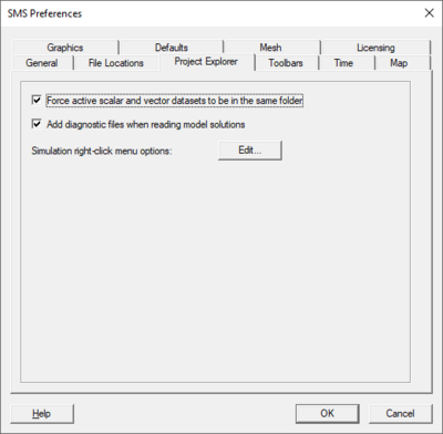
[[Image:SMS Pref Project.png|thumb|none|left|400 px|''SMS Preferences'' dialog showing the ''Project Explorer'' tab.]] | [[Image:SMS Pref Project.png|thumb|none|left|400 px|''SMS Preferences'' dialog showing the ''Project Explorer'' tab.]] | ||
This tab allows the specification of preferences for interacting with the data tree in the Project Explorer. | |||
The ''Project Explorer'' tab provides preferences for interacting with the data tree in the Project Explorer. Supported options include: | The ''Project Explorer'' tab provides preferences for interacting with the data tree in the Project Explorer. Supported options include: | ||
* ''Force active scalar and vector datasets to be in the same folder'' – When this option is selected, the scalar and vector datasets selected for any geometric object (mesh, grid, scatter set, boundary fitted grid, ...) must be in the same folder. If a scalar dataset is selected in a different folder in the Project Explorer, the first vector dataset (if one exists) will also be selected. If a vector dataset in a different folder is selected, the first scalar dataset in that folder will be selected. | * ''Force active scalar and vector datasets to be in the same folder'' – When this option is selected, the scalar and vector datasets selected for any geometric object (mesh, grid, scatter set, boundary fitted grid, ...) must be in the same folder. If a scalar dataset is selected in a different folder in the Project Explorer, the first vector dataset (if one exists) will also be selected. If a vector dataset in a different folder is selected, the first scalar dataset in that folder will be selected. | ||
* ''Add diagnostic files when reading model solutions.'' – If this toggle is selected, SMS will add an entry to the Project Explorer data tree to link to the diagnostic (text messages) file associated with a numerical simulation. Not all numerical engines support this type of a file. | * ''Add diagnostic files when reading model solutions.'' – If this toggle is selected, SMS will add an entry to the Project Explorer data tree to link to the diagnostic (text messages) file associated with a numerical simulation. Not all numerical engines support this type of a file. | ||
* ''Simulation right-click menu options'' – Clicking the '''Edit''' button next to this option will open the ''Simulation Menu Preferences'' dialog. | * ''Simulation right-click menu options'' – Clicking the '''Edit''' button next to this option will open the ''Simulation Menu Preferences'' dialog. | ||
* future | |||
* future | |||
* future | |||
* future | |||
* future | |||
* future | |||
* future | |||
== Toolbars == | == Toolbars == | ||
Revision as of 21:32, 22 April 2022
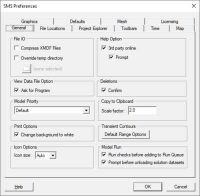
The Edit | Preferences command brings up the Preferences dialog. The Preferences dialog contains the following tabs:
General
- File IO
- Compress XMDF Files – Use compression when saving XMDF files.
- Override temp directory – Specify the location where SMS temporary files are written.
- Help Option
- Use local help – Option to access the CHM file include with SMS when the Help button in a dialog is pressed.
- Use online help – Option to access the XMS Wiki when the Help button in a dialog is pressed.
- 3rd party online – Allows specifying third-party help using the Dynamic Model Interface Schema.
- Prompt
- View Data File Option
- Ask for Program – SMS will prompt to specify the program used to open a data file when the File | View Data File command is called.
- Deletions
- Confirm Deletions – Choose to be prompted to confirm the deletion whenever a set of selected objects is about to be deleted. This is meant to prevent accidental deletion of objects.
- Model Priority – Models can be launched using a particular process priority. This priority specifies how the operating system should treat the process. We recommend using the "Above Normal", "Normal", or "Below Normal" options in most circumstances. The options are as follows:
- "Realtime" – Highest priority. May cause machine to become unresponsive. Use with extreme care.
- "High" – Only allows realtime process to go before it. Can use nearly all CPU cycles. Use with extreme care.
- "Above Normal" – Takes priority over normal processes. Will take CPU cycles before normal applications do.
- "Normal" – No special scheduling takes place. This is the normal default.
- "Below Normal" – Allows processes with normal priority to run first, but runs before low priority processes.
- "Low" – The process will only run when the system is idle.
- "Default" – The process will be launched with the same priority as it's parent (SMS in this case).
- Copy to Clipboard
- Scale factor – When copying the contents of the main graphics window to clipboard, the resolution can be increase by specifying a scale factor greater than 1.0.
- Print Options – When printing the contents of the main graphics window to a printer, the background color of the graphics window will be treated as if it is white when this option is selected.
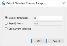
- Transient Contours – The Default Range Options button launches the Default Transient Contour Range dialog. This dialog allows the user to determine how SMS computes the default range for contour options. The factory preference is to use union of all time steps in the current dataset. However, some models include spin up or ramp times during which the numerical results are not in a typical range. For example, a model which supports dry initial conditions will simulate a surge or flood wave as the water moves through the domain initially. This rapidly varied front could result in much larger than typical velocities. This option provides an method for instructing SMS to skip these atypical or unreasonable values from impacting the default ranges of the contours computed. The option for default contour range is display in the contour options dialog box. Options include:
- Skip (n) time steps – This option will skip the first n time steps. If less than n time steps exist in the current dataset, the last time step is used. Setting this value to a large integer would cause SMS to always use the last time step range as the default range.
- Skip (n) hrs – This option will skip the first n hours of time steps. If less than n hours of data exist in the current dataset, the last time step is used. Setting this value to a large floating point number would cause SMS to always use the last time step range as the default range.
- Use current time step – This option instructs SMS to always use the range of the current time step as the default range.
- Icon Options – Allows changing the display size of icons in the interface.
- Icon size – Specifies the display size for icons.
- "Auto" – The default icon display size.
- "Small" – Causes the icons to be displayed at a smaller size; around 9 pixels wide.
- "Large" – Causes the icons to be displayed at a larger size; around 27 pixels wide.
- Icon size – Specifies the display size for icons.
- Model Run – Options for processes that can run in conjunction with the model run.
- Run checks before adding to Run Queue – When turned on, the model check will run before the model is added to the run queue. If errors are found, a prompt will appear and the model will not be added to the run queue.
- Prompt before unloading solution datasets – When turned on, a warning will appear if the solution datasets need to be removed from the project before the model can run, for example when running the same simulation again. When turned off, the solution datasets will be removed without any warning.
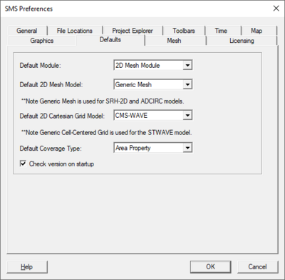
Defaults
The Defaults tab was previously referred to as the Startup tab. It allows defining which modules and models are active by default when SMS is launched.
- Default Module – In this combo box, specify which module is active module at startup.
- Default 2D Mesh Model – This combo box is somewhat deprecated. When SMS operated on a mesh based modeling system, each mesh would be associated with a specific numeric engine. With the transition to the Simulation based approach, the mesh is a generic entity that can be applied to simulations of multiple types at the same time. For this reason, the default option for this toggle is a Generic Mesh and we strongly recommend that this not change. Currently this active 2D Mesh Module Model at startup can be set to:
- Generic Mesh - this is the recommended option. A mesh of this type can be applied to any simulation based model.
- CGWAVE - this option is retained for use with CGWAVE phase resolved wave interaction models. The conversion of this engine to simulation based approach is under consideration.
- TABS - this option is retained for historic RMA2/RMA4 models. This feature is scheduled for deprecation.
- Generic Model - this option is retained for historic generic model interface models. This option is scheduled for deprecation.
- ADH - this option is being transitioned to a simulation based interface that will be incorporated in version 13.2. The mesh based simulation should not be used after version 13.1.
- Default 2D Cartesian Grid Model – This combo box is also moving towards deprecation due to transition to the Simulation based approach. For this reason, the default option for this toggle is a Generic Cell-Centered Grid which is used for multiple engines including STWAVE and CMS-Wave. Currently this active 2D Cartesian Grid Model at startup can be set to:
- BOUSS2D - this option is retained for use with the BOUSS-2D phase resolved wave interaction models. The conversion of this engine to simulation based approach is under consideration.
- TUFLOW - this option is retained for use with the TUFLOW classic engine. Conversion to a generic based approach is underway.
- WAM - this option is scheduled for conversion to the simulation based approach.
- Default Coverage Type – In this combo box, specify the active Map Module Coverage Type at startup. Currently, SMS always requires at least one coverage to exist in a session. This coverage type controls the type of that new, blank coverage as well as the default type of newly created coverages. There is an option to specify or change the type of the coverage as it is being created. Existing coverages can also be converted to another type at any time.
- Check version on startup – This command instructs SMS to check, via an internet query for an update to SMS from Aquaveo. If the user machine is behind a firewall that does not allow access to the internet, this command will not function properly.
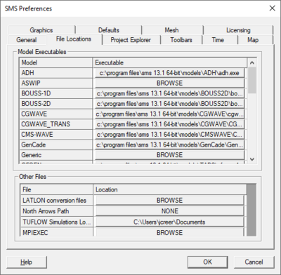
File Locations
This tab allows the specification of the location of applications and folders that may be used in the course of an SMS session. Once a new target is specified, SMS remembers that location for all future instances of the application until the program is reinstalled or the location is changed manually. This tab will only shows models with an active license.
- Model Executables – This table occupies the upper section of the tab and allows specifying the location of numerical model executables. With the conversion to simulation based modeling, many engines/executables are now stored in the Python installation installed for SMS. Numeric engines that have not been converted are still installed in the models directory inside the SMS installation folder. Some models include only a single executable, others include two, three or more. The installation will include a sub-folder for each model installed with the SMS installation. Both 32 and 64-bit versions of most numerical engines may be available.
Note: The list of supported engines is not static. It changes based on licensing as well as dynamic model interfaces that can be loaded at run time for SMS.
- Other Files – This table occupies the lower section of the tab and allows specifying the location of resource files that may be utilized during an SMS session. These files include:
- LATLON conversion files: this is a utility to assist in the conversion from geographic projections/distances to georectified values.
- The location of a resource folder containing bitmaps of North Arrow representation to be used by the annotation tools. Aquaveo provides several default bitmaps. Individual users can create custom bitmaps for this use. By default this folder is installed beneath the SMS installation folder.
- The path to the log file for TUFLOW simlations. This option will be deprecated when the TUFLOW interface is converted to the standard simulation based modeling approach. Initially, TUFLOWFV will appear but TUFLOW classic will be converted in turn.
- The path to the Intel MPIEXEC application which is utilized for ADCIRC and similar MPI parallel process execution.
- The path to the Microsoft MPIEXEC application which is utilized for AdH and similar MPI parallel process execution.
Note: Various other resources that are currently under investigation. Historically we had a link to the LeProvost tidal database. This feature has been replaced with a more general tidal database tool that can access not only the Leprovost and ADCIRC tidal data bases, but also the FES and TPX0 databases.
Project Explorer
This tab allows the specification of preferences for interacting with the data tree in the Project Explorer.
The Project Explorer tab provides preferences for interacting with the data tree in the Project Explorer. Supported options include:
- Force active scalar and vector datasets to be in the same folder – When this option is selected, the scalar and vector datasets selected for any geometric object (mesh, grid, scatter set, boundary fitted grid, ...) must be in the same folder. If a scalar dataset is selected in a different folder in the Project Explorer, the first vector dataset (if one exists) will also be selected. If a vector dataset in a different folder is selected, the first scalar dataset in that folder will be selected.
- Add diagnostic files when reading model solutions. – If this toggle is selected, SMS will add an entry to the Project Explorer data tree to link to the diagnostic (text messages) file associated with a numerical simulation. Not all numerical engines support this type of a file.
- Simulation right-click menu options – Clicking the Edit button next to this option will open the Simulation Menu Preferences dialog.
- future
- future
- future
- future
- future
- future
- future
Toolbars
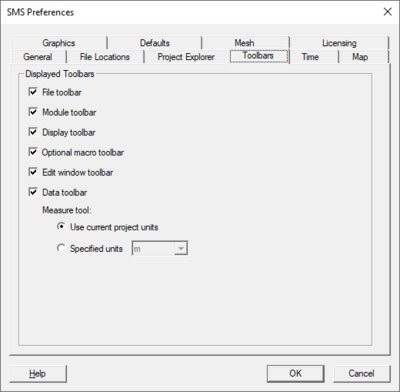
The toolbar tab allows controlling the status and position of each toolbar in SMS at startup. These positions/status values can be changed by dragging each individual toolbar during a session of SMS. The toggle box to the left of the toolbar controls whether the toolbar will be visible when SMS start. The toolbars included in this feature include:
- File Toolbar – This toolbar includes the four File menu commands (Open, Save, Print and Delete). By default it is visible and it appears at the top of the screen between the menu bar and the Project Explorer.
- Module Toolbar – This toolbar includes the modules. In early versions of SMS it was the only way to switch between modules and was commonly used for navigation. With the addition of the Project Explorer, the module toolbar was less essential. It is still ON by default, but was moved to the bottom of the screen below the Project Explorer as a default location.
- Display Toolbar – This toolbar includes the principal Display menu commands (Refresh, Frame, Display Options and Plan View). By default it is visible and it appears at the top of the screen between the menu bar and the project explorer.
- Optional Macro – This toolbar includes the secondary Display menu commands (Lighting, Contour Options, Vector Options, Info, Plot, and Web data). By default it is visible and it appears at the bottom of the graphics window.
- Edit Window – This toolbar includes the edit fields for viewing/specifying the coordinates of a selected point/vertex/cell and the associated dataset values. It appears at the top of the Graphics Window.
- Data Toolbar – This toolbar includes the Measure tool and Get Image tool.
Time
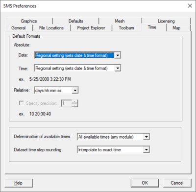
See the Time Steps window article for an explanation of absolute and relative time. The default format of the time steps in the Time Steps window can be set.
Available times options
This option controls which times are displayed in the Time Steps window. The available options are:
- Active datasets (current module only) – The times displayed in the Time Steps window are based only upon the active scalar and vector datasets in the current module. If neither of these datasets is transient, the Time Steps window will not be displayed.
- All available times (all modules) – The times displayed in the Time Step Window are based upon times used by any transient object in SMS (includes datasets, some kinds of coverages, and PTM particle sets). All of the times from each of the objects will be used regardless of whether or not the object is active or visible.
Dataset time step rounding
The dataset being used for contours, vectors, or other display option may not have a time step that corresponds exactly with the time currently chosen in the Time Steps window. When this happens, SMS has two options for determining the values used by the dataset. These options are:
- "Interpolate to exact time" – Interpolate the dataset values for the selected time step from the nearest time steps before or after the display time. If the display time is before/after all of the time steps the nearest time step is used.
- "Use nearest time" – The dataset time step nearest the display time will be used (no interpolation).
Map
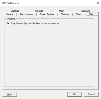
This tab includes an options to Snap feature objects to displayed inactive coverage nodes and vertices when creating new feature objects. This allows creating objects in one coverage that are aligned with objects in another coverage.
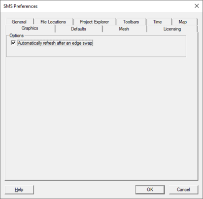
Graphics
- Options
- Automatically refresh after an edge swap
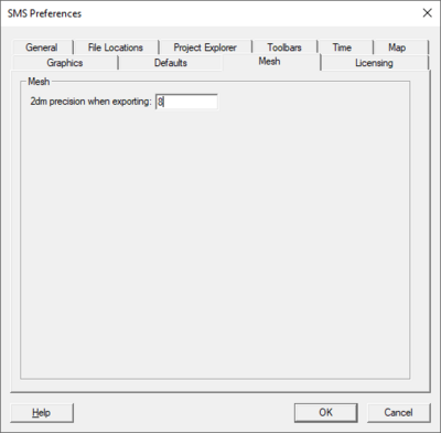
Mesh
This tab includes an option to specify the precision that will be used to output "2dm" mesh files from SMS.
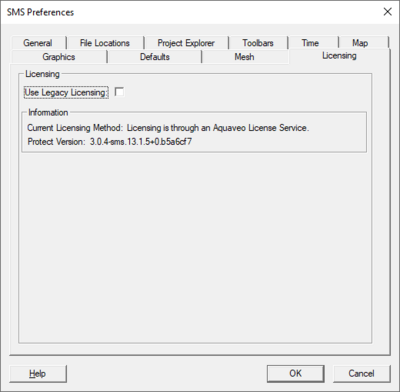
Licensing
This tab shows information about the application license.
- Use Legacy Licensing – Turning on will revert to using older licenses.
- Information – Shows information about the license being used.
Related Topics
SMS – Surface-water Modeling System | ||
|---|---|---|
| Modules: | 1D Grid • Cartesian Grid • Curvilinear Grid • GIS • Map • Mesh • Particle • Quadtree • Raster • Scatter • UGrid |  |
| General Models: | 3D Structure • FVCOM • Generic • PTM | |
| Coastal Models: | ADCIRC • BOUSS-2D • CGWAVE • CMS-Flow • CMS-Wave • GenCade • STWAVE • WAM | |
| Riverine/Estuarine Models: | AdH • HEC-RAS • HYDRO AS-2D • RMA2 • RMA4 • SRH-2D • TUFLOW • TUFLOW FV | |
| Aquaveo • SMS Tutorials • SMS Workflows | ||
