GMS:UGrid Display Options: Difference between revisions
From XMS Wiki
Jump to navigationJump to search
No edit summary |
No edit summary |
||
| (8 intermediate revisions by 2 users not shown) | |||
| Line 1: | Line 1: | ||
{{UGrid links}} | {{UGrid links}} | ||
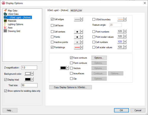
The display options of UGrid data that GMS displays on the screen can be controlled through the ''UGrid Data'' tab of the [[GMS:Display Options|''Display Options'']] dialog. This dialog is opened by right-clicking on the [[File:UGrid 2D Folder.svg|16 px]] [[File:UGrid 3D Folder.svg|16 px]] "UGrid Data" item in the [[GMS:Project Explorer|Project Explorer]] and selecting the '''Display Options''' command. It can also be accessed from the from the ''Display'' menu or the | The display options of UGrid data that GMS displays on the screen can be controlled through the ''UGrid Data'' tab of the [[GMS:Display Options|''Display Options'']] dialog. This dialog is opened by right-clicking on the [[File:UGrid 2D Folder.svg|16 px]] [[File:UGrid 3D Folder.svg|16 px]] "UGrid Data" item in the [[GMS:Project Explorer|Project Explorer]] and selecting the '''Display Options''' command. It can also be accessed from the from the ''Display'' menu or the '''Display Options''' [[File:Display Options Macro.svg|16 px]] macro. The following table describes the display options available for the UGrid module. | ||
When multiple UGrids exist in a project, each UGrid will be shown in the list on the left side of the ''Display Options'' dialog. The display options for each UGrid in the project can be set separately. There is also a tab for general UGrid display options. Editing these options does not directly affect any existing UGrid, but it will affect any newly created UGrid. | |||
{| class="wikitable" | {| class="wikitable" | ||
! width="125" | Display Option !! Description | ! width="125" | Display Option !! Description | ||
|- | |- | ||
| Cell edges || | | Cell edges || Displays the edges of cells. The button next to the option opens a ''Line Properties'' dialog for adjusting the style, size, and color of the Cell edges. | ||
|- | |- | ||
| Cell faces || | | Cell faces || Displays the cells filled with their assigned material color. | ||
|- | |- | ||
| Cell centers || | | Cell centers || Displays a point at the center of every cell. | ||
|- | |- | ||
| Points || Points are the corners of cells, or simply 3D points not attached to cells. A symbol can be displayed at these locations. If Point contours are on, the color of the symbol will be determined by the data and the contour options. | | Points || Points are the corners of cells, or simply 3D points not attached to cells. A symbol can be displayed at these locations. If Point contours are on, the color of the symbol will be determined by the data and the contour options. | ||
|- | |- | ||
| Inactive points || | | Inactive points || Displays points that correspond with an inactive dataset value. | ||
|- | |||
| Pointstrings || Displays pointstrings (nodestrings) created on the UGrid. | |||
|- | |||
| Off cells || Displays off cells. | |||
|- | |- | ||
| UGrid | | UGrid boundary || Displays an edge for each of the edges on the exterior of the set of all cells (visible or invisible) which corresponds to a discontinuity in the UGrid exterior. This display option provides a helpful spatial context when displaying isosurfaces or cross sections. | ||
|- | |- | ||
| Feature angle || | | Feature angle || Used only when the ''UGrid boundary'' option is selected. This angle represents a threshold angle at which an edge of the boundary will be displayed. If for example, an angle of 45 degrees is defined, any edge of the UGrid which divides two cell faces that are at an angle greater than 45 degrees to each other is not displayed. | ||
|- | |- | ||
| Point numbers || | | Point numbers || Displays the ID associated with each point next to the point. | ||
|- | |- | ||
| Cell numbers || | |Point scalar values || Displays the scalar values of the active dataset for each point next to the point. | ||
|- | |||
| Cell numbers || Displays the ID associated with each cell at the centroid of the cell. | |||
|- | |- | ||
| | |Cell scalar values || Displays the scalar values of the active dataset for each cell. | ||
|- | |- | ||
| Face contours || Most of the objects supported by GMS can be contoured by turning on the [[GMS:Contour Options|''Contour Options'']] in the ''Display Options'' dialog. When an object is contoured, the values associated with the active dataset for the object are used to generate the contours. | | Face contours || Most of the objects supported by GMS can be contoured by turning on the [[GMS:Contour Options|''Contour Options'']] in the ''Display Options'' dialog. When an object is contoured, the values associated with the active dataset for the object are used to generate the contours. | ||
|- | |- | ||
| Point contours || The same [[GMS:Contour Options|Contour Options]] but applied to points. | | Point contours || The same [[GMS:Contour Options|Contour Options]] but applied to points. | ||
|- | |- | ||
| Vectors || | | Vectors || Displays vector arrows using the active vector dataset. | ||
|- | |- | ||
| Isosurfaces || Isosurfaces are the 3D equivalent of a contour line. An isosurface is a surface of constant value extracted from a 3D dataset. | | Isosurfaces || Displays isosurfaces. Isosurfaces are the 3D equivalent of a contour line. An isosurface is a surface of constant value extracted from a 3D dataset. | ||
|- | |- | ||
| Clip || Creates a clipping widget that can be used to hide part of the UGrid. Clicking the '''Options''' button will bring up the ''UGrid Clip Settings'' dialog. The options include setting the widget to be a plane, which can be manipulated with the mouse in the Graphics Window, or to be a scalar or scalar range, which work like isosurfaces. Whole cells or partial cells can be clipped. | | Clip || Creates a clipping widget that can be used to hide part of the UGrid. Clicking the '''Options''' button will bring up the [[GMS:UGrid_Display_Options#UGrid_Clip_Settings|''UGrid Clip Settings'']] dialog. The options include setting the widget to be a plane, which can be manipulated with the mouse in the Graphics Window, or to be a scalar or scalar range, which work like isosurfaces. Whole cells or partial cells can be clipped. | ||
|- | |- | ||
| Copy Display Options to UGrid(s) || | | Copy Display Options to UGrid(s) || The current UGrid ''Display Options'' can be copied to other UGrids. This button brings up a dialog to select the UGrids that the display options will be copied to. | ||
|} | |} | ||
[[File:Display3DUGrid. | [[File:Display3DUGrid.png|thumb|none|left|500 px|The ''Display Options'' dialog showing the ''3D UGrid'' tab.]] | ||
==UGrid Clip Settings== | ==UGrid Clip Settings== | ||
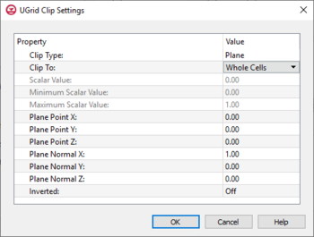
[[File:UGridClipSettings.png|thumb| | [[File:UGridClipSettings.png|thumb|350 px|The ''UGrid Clip Settings'' dialog]] | ||
The ''Ugrid Clip Settings'' dialog allows setting parameters for clipping the UGrid display. The dialog has the following options: | The ''Ugrid Clip Settings'' dialog allows setting parameters for clipping the UGrid display. The dialog has the following options: | ||
*''Clip Type'' – Can be set to "Plane", "Scalar", or "Scalar Range". | *''Clip Type'' – Can be set to "Plane", "Scalar", or "Scalar Range". | ||
| Line 47: | Line 55: | ||
**"Scalar" – Defines the clipping area based on a single value. | **"Scalar" – Defines the clipping area based on a single value. | ||
**"Scalar Range" – Defines the clipping area based on a minimum and maximum value. | **"Scalar Range" – Defines the clipping area based on a minimum and maximum value. | ||
*''Clip To'' – Set the clipping to use "Whole Cells" or "Partial Cells". | *''Clip To'' – Set the clipping to use "Whole Cells" or "Partial Cells". | ||
**"Whole Cells" will display the entire cell when the majority of the cell is inside the clipping plane. | |||
**"Partial Cells" will create a smoother display as portions of cells inside the clipping plane will be displayed. | |||
*''Scalar Value'' – Creates a clipping region based on the set scalar value. | *''Scalar Value'' – Creates a clipping region based on the set scalar value. | ||
*''Minimum Scalar Value'' – The lowers scalar value for the clipping range. | *''Minimum Scalar Value'' – The lowers scalar value for the clipping range. | ||


