SMS:ADCIRC Weirs and Island Barriers: Difference between revisions
| Line 43: | Line 43: | ||
==Extract Elevations== | ==Extract Elevations== | ||
Data entered in as weir or island barrier boundary condition data can be used to create arcs and/or set grid cell elevations | Data entered in as weir or island barrier boundary condition data can be used to create arcs in a coverage and/or set grid cell elevations that correspond to the weir or barrier. To use this functionality, select the '''Extract Weir Elevations...''' option from the ''Nodestring'' menu. This will open the ''Extract Weir Elevations'' dialog. Here the user can choose to use only the selected weir or barrier nodestrings, or use all weir or barrier nodestrings in the mesh. | ||
After selecting '''OK''' in the dialog, SMS will compute elevations at the midpoint of each node pair in the BC. This is done by first interpolating between the node elevations of each pair, and then subtracting the weir/barrier elevation (which were specified in the weir or island barrier parameters) from that value. | |||
If the coverage option is used, SMS will create arcs that represent the weirs or barriers on the specified coverage. The computed elevations will be assigned along the arc. If one or more grids are used, SMS will set the elevation values for all grid cells that lie underneath the midpoints to match the computed values. | |||
{{Template:Navbox SMS}} | {{Template:Navbox SMS}} | ||
Revision as of 15:11, 10 October 2014
ADCIRC Weirs and Island Barriers
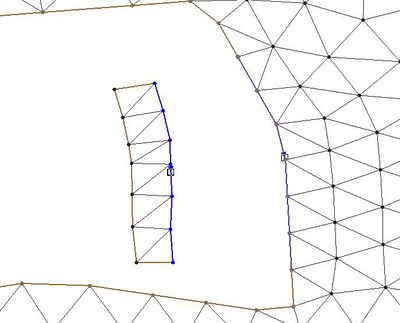
An ADCIRC weir is a boundary type that are assigned to two nodestrings on an ADCIRC mesh. A weir comprises of two nodestrings next to each other with an equal amount of nodes on each nodestrings. In order to add a weir in ADCIRC, there must be two adjacent nodestrings available as shown in figures 1 and 2 below.
The number of nodes on each nodestrings must be of an equal amount or a weir cannot be assigned. See figure 3 below. Each node and it's corresponding node on the parallel nodestring will form a node pair.
Weir Options
Once two nodestrings with same number of nodes exist, they can be assigned as a weir by selecting both weirs and selecting Assign BC. The Nodestring attributes will open. By selecting Weir and then clicking on the Parameters button, the Weir Options dialog will open. The dialog shows the different Node pairs and elevation for each node pair.
Elevation
Elevation of each node pair. The elevation for each node pair can be entered manually or can be interpolated from a dataset
Super
Weir flow coefficients for super critical flow. A typical value for this is 1.0.
Sub
Weir flow coefficients for sub critical flow. A typical value for this is 1.0.
- Pipe
- Elevation = elevation of the pipe
- Diameter = diameter of pipe
- Coefficient = f (L/D)
where
– is the length of the pipe
– is the hydraulic diameter of the pipe (for a pipe of circular section, this equals to the internal diameter of the pipe)
– is a dimensionless coefficient called the Darcy friction factor. It can be found from a Moody diagram or by solving the Colebrook equation.
Interpolate Elevations Button
Clicking on the Interpolate Elevations button opens the XY Series Editor. The XY Series Editor can be used to generate and edit curves defined by a list of x and y coordinates. The curve can be created and edited by directly editing the xy coordinates using a spreadsheet list of the coordinates. An entire list of curves can be generated and edited with the Editor and curves can be imported from and exported to text files for future use. A user can also paste the xy data directly to the spreadsheet.
Extract Elevations
Data entered in as weir or island barrier boundary condition data can be used to create arcs in a coverage and/or set grid cell elevations that correspond to the weir or barrier. To use this functionality, select the Extract Weir Elevations... option from the Nodestring menu. This will open the Extract Weir Elevations dialog. Here the user can choose to use only the selected weir or barrier nodestrings, or use all weir or barrier nodestrings in the mesh.
After selecting OK in the dialog, SMS will compute elevations at the midpoint of each node pair in the BC. This is done by first interpolating between the node elevations of each pair, and then subtracting the weir/barrier elevation (which were specified in the weir or island barrier parameters) from that value.
If the coverage option is used, SMS will create arcs that represent the weirs or barriers on the specified coverage. The computed elevations will be assigned along the arc. If one or more grids are used, SMS will set the elevation values for all grid cells that lie underneath the midpoints to match the computed values.
SMS – Surface-water Modeling System | ||
|---|---|---|
| Modules: | 1D Grid • Cartesian Grid • Curvilinear Grid • GIS • Map • Mesh • Particle • Quadtree • Raster • Scatter • UGrid |  |
| General Models: | 3D Structure • FVCOM • Generic • PTM | |
| Coastal Models: | ADCIRC • BOUSS-2D • CGWAVE • CMS-Flow • CMS-Wave • GenCade • STWAVE • WAM | |
| Riverine/Estuarine Models: | AdH • HEC-RAS • HYDRO AS-2D • RMA2 • RMA4 • SRH-2D • TUFLOW • TUFLOW FV | |
| Aquaveo • SMS Tutorials • SMS Workflows | ||


