AHGW:Polygon to TIN: Difference between revisions
From XMS Wiki
Jump to navigationJump to search
(Created page with "350px|thumb|right|''Polygon to TIN'' dialog The ''Polygon to TIN'' tool is accessed by double-clicking on "File:Arc...") |
No edit summary |
||
| (One intermediate revision by one other user not shown) | |||
| Line 1: | Line 1: | ||
[[File: | [[File:ArcGIS Pro Polygon to TIN.png|350px|thumb|right|''Polygon to TIN'' tool in the ''Geoprocessing'' pane]] | ||
The ''Polygon to TIN'' tool is accessed by double-clicking on "[[File: | The ''Polygon to TIN'' tool is accessed by double-clicking on "[[File:ArcGISPro Toolbx Tool.png|16 px]] Polygon to TIN" under the "[[File:ArcGISPro Toolset.png|16 px]] TIN" toolset under the "[[File:ArcGISPro Toolset.png|16 px]] Subsurface Analyst" toolset under the "[[File:ArcGISPro Toolbx Item.png|16 px]] ArcHydroGroundwater.pyt" toolbox. This tool creates creates a projection TIN for use with the [[AHGW:Rasters to GeoVolumes|Rasters to GeoVolumes]] tool. | ||
:'''''ArcGIS Notes''''' – In older versions of ArcGIS, this tool is accessed through the "Arc Hydro Groundwater Tools" toolbox. The tool appears as a dialog, not a pane. | |||
The following fields are available. Required fields are marked with a [[File:ArcGIS required - green circle icon.png|8px]] icon. Fields marked with a [[File:ArcGIS | :The icons vary between ArcGIS and ArcGIS Pro. | ||
*[[File:ArcGIS | The following fields are available. Required fields are marked with a [[File:ArcGIS Pro Red Required Symbol.png|8 px]] icon. In ArcGIS, they are marked with a [[File:ArcGIS required - green circle icon.png|8px]] icon. Fields marked with a [[File:ArcGIS Pro Warning Red.png|12 px]] icon may either not be supported or the table doesn't exist. | ||
*[[File:ArcGIS | *[[File:ArcGIS Pro Red Required Symbol.png|8 px]] ''Input polygon feature'' – Click the [[File:ArcGISPro Open.png|16 px]] button to bring up the ''Input polygon feature'' dialog in order to specify the polygon defining the boundary of the TIN to be created. | ||
*[[File:ArcGIS | *[[File:ArcGIS Pro Red Required Symbol.png|8 px]] ''TIN triangle spacing'' – Enter the spacing used to build equilateral triangles inside the TIN. Internal triangle edges will have a length equal to this spacing. The length of the edges along the polygon boundary will be irregular. | ||
*'' | *[[File:ArcGIS Pro Red Required Symbol.png|8 px]] ''Output projection TIN'' – Click the [[File:ArcGISPro Open.png|16 px]] button to bring up the ''Output projection TIN'' dialog in order to specify the polygon defining the boundary of the TIN to be created. | ||
*'' TIN spatial reference'' – Optional. Click the [[File:ArcGISPro SlctCoordnateSystm.png|16 px]] button to bring up the ''Coordinate System'' dialog where a spatial reference system can be selected. | |||
{{Navbox AHGW}} | {{Navbox AHGW}} | ||
[[Category:AHGW Subsurface Analyst]] | [[Category:AHGW Subsurface Analyst]] | ||
Latest revision as of 16:55, 14 April 2023
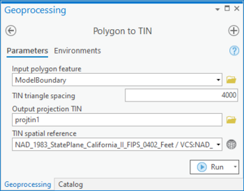
The Polygon to TIN tool is accessed by double-clicking on "![]() Polygon to TIN" under the "
Polygon to TIN" under the "![]() TIN" toolset under the "
TIN" toolset under the "![]() Subsurface Analyst" toolset under the "
Subsurface Analyst" toolset under the "![]() ArcHydroGroundwater.pyt" toolbox. This tool creates creates a projection TIN for use with the Rasters to GeoVolumes tool.
ArcHydroGroundwater.pyt" toolbox. This tool creates creates a projection TIN for use with the Rasters to GeoVolumes tool.
- ArcGIS Notes – In older versions of ArcGIS, this tool is accessed through the "Arc Hydro Groundwater Tools" toolbox. The tool appears as a dialog, not a pane.
- The icons vary between ArcGIS and ArcGIS Pro.
The following fields are available. Required fields are marked with a ![]() icon. In ArcGIS, they are marked with a
icon. In ArcGIS, they are marked with a ![]() icon. Fields marked with a
icon. Fields marked with a ![]() icon may either not be supported or the table doesn't exist.
icon may either not be supported or the table doesn't exist.
 Input polygon feature – Click the
  button to bring up the Input polygon feature dialog in order to specify the polygon defining the boundary of the TIN to be created.
 TIN triangle spacing – Enter the spacing used to build equilateral triangles inside the TIN. Internal triangle edges will have a length equal to this spacing. The length of the edges along the polygon boundary will be irregular.
 Output projection TIN – Click the
  button to bring up the Output projection TIN dialog in order to specify the polygon defining the boundary of the TIN to be created.
- TIN spatial reference – Optional. Click the
 button to bring up the Coordinate System dialog where a spatial reference system can be selected.

