SMS:Scatter Menu: Difference between revisions
| (6 intermediate revisions by 2 users not shown) | |||
| Line 21: | Line 21: | ||
==== Overlapping region options ==== | ==== Overlapping region options ==== | ||
* ''Merge all scatter points'' – All scatter points from all scatter sets to be merged are combined into one set and retriangulated. | * ''Merge all scatter points'' – All scatter points from all scatter sets to be merged are combined into one set and retriangulated. | ||
* ''Delete lower priority scatter points'' – In regions where scatter points and triangles overlap, the scatter points and triangles from the lower priority scatter set are deleted. The priority is based on the ''Priority'' column of the ''Select scatter sets to merge'' spreadsheet. The '''Move up''' and '''Move down''' buttons can be used to adjust the priority of the scatter sets when this option is selected. | * ''Delete lower priority scatter points'' – In regions where scatter points and triangles overlap, the scatter points and triangles from the lower priority scatter set are deleted. The priority is based on the ''Priority'' column of the ''Select scatter sets to merge'' spreadsheet. The '''Move up''' and '''Move down''' buttons can be used to adjust the priority of the scatter sets when this option is selected. When this option is selected, the boundary of the higher priority scatter set is forced into the resulting merged scatter set. If the point spacing along this boundary varies greatly from one scatter set to the other, the result will include skinny triangles, which are not recommended. If the triangles become too skinny, numerical issues may result due to floating point precision round off. To address this, a tolerance is specified to delete points from the lower priority scatter set not just inside the higher priority set, but also points outside the higher priority set but within the specified tolerance of the edge of the higher priority set. This lessens the severity of the ''skinny triangle'' issue. | ||
*:Note: historically it has been common to convert DEM/raster datasets to a scatter set in order to create a continuous surface for interpolation. This workflow can result in scatter sets with millions of points and is not numerically stable or efficient. SMS now supports the use of multiple rasters to represent varied resolution for background data. A workflow using rasters is recommended in this case. | |||
** ''Maintain triangulation'' – The triangulation of the original scatter sets is maintained. New triangles are created to connect the original scatter sets into a single, merged scatter set. | ** ''Maintain triangulation'' – The triangulation of the original scatter sets is maintained. New triangles are created to connect the original scatter sets into a single, merged scatter set. | ||
| Line 31: | Line 32: | ||
Active when a scatter point, or group of points, have been selected. This brings up a dialog that allows assigning a unique name to the selected point. | Active when a scatter point, or group of points, have been selected. This brings up a dialog that allows assigning a unique name to the selected point. | ||
===Interpolate to=== | ===Interpolate to=== | ||
Bring ups the ''Interpolation Options'' dialog. | Bring ups the [[SMS:Scatter Interpolation|''Interpolation Options'']] dialog. This dialog is used to interpolate scatter set values to a 2D mesh, Cartesian grid, UGrid, or quadtree. | ||
*2D Mesh – The scatter point [[SMS:Datasets|datasets]] are then interpolated to the mesh nodes using the user specified interpolation options. | |||
* Cartesian Grid – The scatter point function values are then interpolated to the center of each grid cell. | |||
* UGrid – The scatter point function values are then interpolated to the center of each grid cell. | |||
===Interpolate to Scatter=== | ===Interpolate to Scatter=== | ||
Latest revision as of 16:51, 24 September 2024
The items in the Scatter menu in the Scatter module are described below. The menu items all work with the active scatter set unless otherwise noted.
Listed below are the general commands in the Scatter menu.
Scatter Options
Scatter options are accessed through the Scatter menu, Scatter Options dialog in the Scatter Module.
Merge Scatter Sets
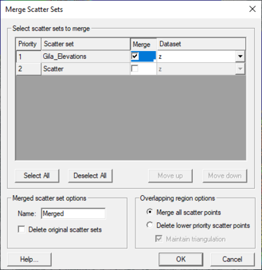
Multiple scatter sets can be merged into a single scatter set using the Merge Scatter Sets dialog. The menu command Scatter | Merge Sets opens the Merge Scatter Sets dialog.
Selecting scatter sets to merge
The Merge Scatter Sets dialog contains a spreadsheet listing all of the scatter sets currently loaded into SMS. Scatter sets to merge are specified by checking the Merge box in the Merge column of the spreadsheet. When merging scatter sets, only one dataset is transferred to the merged scatter set. The dataset to be transferred is specified for each scatter set in the Dataset column of the spreadsheet.
The Priority column of the spreadsheet is only used if the overlapping region option is set to Delete lower priority scatter points. This option is explained below.
Merge Options
The following options are available when merging scatter sets:
- Name – Specify the name for the new, merged scatter set.
- Delete original scatter sets – The scatter sets to be merged are deleted after the new, merged set is created.
Overlapping region options
- Merge all scatter points – All scatter points from all scatter sets to be merged are combined into one set and retriangulated.
- Delete lower priority scatter points – In regions where scatter points and triangles overlap, the scatter points and triangles from the lower priority scatter set are deleted. The priority is based on the Priority column of the Select scatter sets to merge spreadsheet. The Move up and Move down buttons can be used to adjust the priority of the scatter sets when this option is selected. When this option is selected, the boundary of the higher priority scatter set is forced into the resulting merged scatter set. If the point spacing along this boundary varies greatly from one scatter set to the other, the result will include skinny triangles, which are not recommended. If the triangles become too skinny, numerical issues may result due to floating point precision round off. To address this, a tolerance is specified to delete points from the lower priority scatter set not just inside the higher priority set, but also points outside the higher priority set but within the specified tolerance of the edge of the higher priority set. This lessens the severity of the skinny triangle issue.
- Note: historically it has been common to convert DEM/raster datasets to a scatter set in order to create a continuous surface for interpolation. This workflow can result in scatter sets with millions of points and is not numerically stable or efficient. SMS now supports the use of multiple rasters to represent varied resolution for background data. A workflow using rasters is recommended in this case.
- Maintain triangulation – The triangulation of the original scatter sets is maintained. New triangles are created to connect the original scatter sets into a single, merged scatter set.
Merge Report
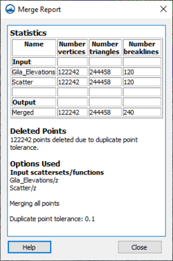
When the merge finishes a merge report will be displayed on the screen. This report shows statistics for the scatter sets that were merge such as number of vertices and triangles before and after the merge. If desired vertices are being deleted, check the duplicate points tolerance. This is found in the Scatter→Scatter Options dialog.
Assign Point Name
Active when a scatter point, or group of points, have been selected. This brings up a dialog that allows assigning a unique name to the selected point.
Interpolate to
Bring ups the Interpolation Options dialog. This dialog is used to interpolate scatter set values to a 2D mesh, Cartesian grid, UGrid, or quadtree.
- 2D Mesh – The scatter point datasets are then interpolated to the mesh nodes using the user specified interpolation options.
- Cartesian Grid – The scatter point function values are then interpolated to the center of each grid cell.
- UGrid – The scatter point function values are then interpolated to the center of each grid cell.
Interpolate to Scatter
Interpolating on scatter set to another scatter set has three options:
Interpolate to Scatter Grid
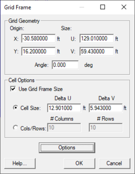
If a scattered dataset exists, the Interpolate to Scatter Grid menu item (Scatter module, Scatter menu) brings up the Grid Frame dialog. This dialog, positions the purple grid frame and sets up the number of rows and columns in the grid. After clickingOK, a new scatter set is created with scatter points at the corners of each grid cell. The original scatter set is interpolated to the new scatter grid set using linear interpolation.
Using the scatter grid is a form of data decimation: a dense scatter set can be represented as a less dense scatter set.
Interpolate from Other Scatter
This option interpolates one scattered dataset to another set. Two sets must exist for this option to be enabled. An Interpolation dialog appears where the scatter set to interpolate from is selected. That scatter set is interpolated to the active scatter set. The interpolation uses an extrapolation value of "0.0".
Interpolate to Nautical Grid
This option creates a nautical chart. A nautical chart divides a scatter set into bins and finds the maximum, minimum, and average depth over each bin. The Interpolate to Nautical Grid menu item (Scatter module, Scatter menu) brings up the Grid Frame dialog. The dialog positions the purple grid frame and sets up the number of rows and columns in the grid. After clicking OK, a new scatter set is created with scatter points at the center of each grid cell. Three functions are created for each scatter point from the active scalar function of the original scatter set:
- Average – The average depth over each bin.
- Minimum – The minimum depth over each bin.
- Maximum – The maximum depth over each bin.
Requirements to interpolate to a nautical grid include:
- A scatter dataset must exist.
- Active coverage type must allow grid frames to be created. The Cartesian Grid Module model coverage types allow the creation of grid frames.
Interpolate to Map
This option will assign the elevation values from on scatter set to the active map coverage. The Interpolation dialog will appear, where the interpolation method can be selected for assigning elevation data to the map coverage.
Obsolete Commands
The following commands are no longer available in current released of SMS:
- Create Scatter Subset
- All selected points from the original scatter set are moved from the original set into a new scatter set. A prompt will ask for the name of the new scatter set. If all points for the current scatter set are selected, nothing occurs. The two scatter sets, the original and the new, are retriangulated.
- Delete Scatter Set
- This option is found in the Scatter module in the Scatter menu. If one scatter set exists, a prompt will ask if wanting to delete the active scatter set. If more than one scatter set exists, a dialog appears. The scatter sets can be flagged for deletion in this dialog. Double-clicking on a scatter set in the window or pushing the Delete button flags or unflags a scatter set for deletion. Select All or Deselect All will flag or unflag all sets. A set is flagged if the letter "d" appears to the left of the scatter name.
Related Topics
SMS Menu Bars | |
|---|---|
| Standard Menus: | File • Edit • Display • Window • Help |
| Module Menus: | 2D Mesh • Cartesian Grid • Curvilinear Grid • GIS • Map • Particle • Quadtree • Raster • Scatter |
| Model Menus: | ADCIRC • BOUSS-2D • CGWAVE • CMS-Flow • CMS-Wave • FESWMS • Generic Model • GenCade • PTM • RMA2 • RMA4 • SRH-2D • STWAVE • TUFLOW |
SMS – Surface-water Modeling System | ||
|---|---|---|
| Modules: | 1D Grid • Cartesian Grid • Curvilinear Grid • GIS • Map • Mesh • Particle • Quadtree • Raster • Scatter • UGrid |  |
| General Models: | 3D Structure • FVCOM • Generic • PTM | |
| Coastal Models: | ADCIRC • BOUSS-2D • CGWAVE • CMS-Flow • CMS-Wave • GenCade • STWAVE • WAM | |
| Riverine/Estuarine Models: | AdH • HEC-RAS • HYDRO AS-2D • RMA2 • RMA4 • SRH-2D • TUFLOW • TUFLOW FV | |
| Aquaveo • SMS Tutorials • SMS Workflows | ||


