SMS:Patch: Difference between revisions
No edit summary |
|||
| (19 intermediate revisions by the same user not shown) | |||
| Line 1: | Line 1: | ||
[[File:Patch River.png|thumb|300 px|Patch used to define a river channel]] | |||
[[File:Patch at Culvert.png|thumb|300 px|Patch used where a culvert will be modeled]] | |||
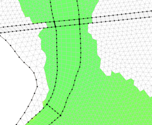
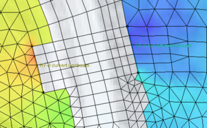
The patch method fills polygons that can be defined as topologic rectangles. The method may combine multiple arcs to define a single side of the patch. A bidirectional coons patching method is used to interpolate from the boundary arcs to interior nodes. Typical applications of this method include river channels and regions aligned to channels. The patching method supports transitioning the number of elements across the channel or from one side to another. Transitions in both directions often result in poorer quality elements and should be avoided if possible. | The patch method fills polygons that can be defined as topologic rectangles. The method may combine multiple arcs to define a single side of the patch. A bidirectional coons patching method is used to interpolate from the boundary arcs to interior nodes. Typical applications of this method include river channels and regions aligned to channels. The patching method supports transitioning the number of elements across the channel or from one side to another. Transitions in both directions often result in poorer quality elements and should be avoided if possible. | ||
The Rectangular Patch mesh generation method requires a polygon made of exactly four arcs, '''''forming four sides'''''. However, very rarely do exactly four arcs make up a polygon. SMS provides a way to define a rectangular patch from a polygon that has more than four arcs by allowing multiple arcs to '''''act as a single patch side'''''. An example of a rectangular patch made up of four sides is shown below. Note that Side 1 and Side 2 are both made from multiple arcs. Hollow squares represent the beginning and ending points of an arc ([[SMS: | The Rectangular Patch mesh generation method requires a polygon made of exactly four arcs, '''''forming four sides'''''. However, very rarely do exactly four arcs make up a polygon. SMS provides a way to define a rectangular patch from a polygon that has more than four arcs by allowing multiple arcs to '''''act as a single patch side'''''. An example of a rectangular patch made up of four sides is shown below. Note that Side 1 and Side 2 are both made from multiple arcs. Hollow squares represent the beginning and ending points of an arc ([[SMS:Feature Objects Types|feature points]]). Filled squares represent intermediate points along the arc ([[SMS:Feature Objects Types|feature vertices]]). | ||
When creating a patch, the number of vertices on parallel arcs should be equal. Often this means aligning vertices on opposite arcs. This can be done using the [[SMS:Arcs#Redistribute_Vertices|''Redistribute Vertices'']] dialog. Using the [[SMS:Arcs#Source_Arc|"Source Arc"]] redistribution method is often preferred. | |||
[[Image:Patch_Mesh_Polygon.jpg|none|frame|Definition of four sides for a rectangular patch]] | [[Image:Patch_Mesh_Polygon.jpg|none|frame|Definition of four sides for a rectangular patch]] | ||
The basic process to define the meshing attributes for a polygon using the Patch method is to: | The basic process to define the meshing attributes for a polygon using the Patch method is to: | ||
# Switch to the [[SMS:Map Module|Map module]] | |||
# Select the menu [[SMS:Map Feature Objects Menu#General Commands|''Feature Objects'' | '''Build Polygons''']] | |||
# Switch to the [[SMS:Map Module Tools|'''Select Polygon''' tool]] | |||
# Select the polygon to set meshing attributes for | |||
# Select the menu [[SMS:2D Mesh Polygon Properties|''Feature Objects'' | '''Attributes''']] | |||
# Set ''Mesh Type'' to ''Patch'' | |||
# Set ''Bathymetry Type' | |||
# Set ''Material Type'' | |||
# Set ''Node Options'' if the polygon consists of more than four arcs | |||
## Switch to the [[SMS:Map Module Tools|'''Select Feature Point''' tool]] in the dialog | |||
## Select the node to "merge" | |||
## In the ''Node Options'' combo box, change the selection to "merge" | |||
## The two arcs meeting at the "merge" node will now be treated as a single arc for the mesh generation within the current polygon. | |||
# Press '''OK''' to exit the dialog and save the polygon attributes | |||
== Related Topics == | == Related Topics == | ||
* [[Paving|Paving Meshing Algorithm]] | * [[SMS:Paving|Paving Meshing Algorithm]] | ||
* [[Scalar Paving Density|Scalar Paving Density Meshing Algorithm]] | * [[SMS:Paving#Scalar Paving Density|Scalar Paving Density Meshing Algorithm]] | ||
* [[SMS: | * [[SMS:Mesh Generation|Mesh Generation]] | ||
* [[SMS: | * [[SMS:2D Mesh Polygon Properties|2D Mesh Polygon Properties dialog]] | ||
* [[SMS:Element Patch Workflow|Element Patch Workflow]] | |||
== External Links == | == External Links == | ||
| Line 33: | Line 39: | ||
{{Template:Navbox SMS}} | {{Template:Navbox SMS}} | ||
[[Category:SMS 2D Mesh| | [[Category:SMS 2D Mesh|Patch]] | ||
Latest revision as of 19:17, 8 April 2020
The patch method fills polygons that can be defined as topologic rectangles. The method may combine multiple arcs to define a single side of the patch. A bidirectional coons patching method is used to interpolate from the boundary arcs to interior nodes. Typical applications of this method include river channels and regions aligned to channels. The patching method supports transitioning the number of elements across the channel or from one side to another. Transitions in both directions often result in poorer quality elements and should be avoided if possible.
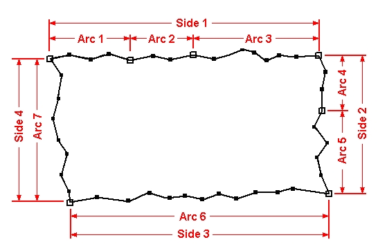
The Rectangular Patch mesh generation method requires a polygon made of exactly four arcs, forming four sides. However, very rarely do exactly four arcs make up a polygon. SMS provides a way to define a rectangular patch from a polygon that has more than four arcs by allowing multiple arcs to act as a single patch side. An example of a rectangular patch made up of four sides is shown below. Note that Side 1 and Side 2 are both made from multiple arcs. Hollow squares represent the beginning and ending points of an arc (feature points). Filled squares represent intermediate points along the arc (feature vertices).
When creating a patch, the number of vertices on parallel arcs should be equal. Often this means aligning vertices on opposite arcs. This can be done using the Redistribute Vertices dialog. Using the "Source Arc" redistribution method is often preferred.
The basic process to define the meshing attributes for a polygon using the Patch method is to:
- Switch to the Map module
- Select the menu Feature Objects | Build Polygons
- Switch to the Select Polygon tool
- Select the polygon to set meshing attributes for
- Select the menu Feature Objects | Attributes
- Set Mesh Type to Patch
- Set Bathymetry Type'
- Set Material Type
- Set Node Options if the polygon consists of more than four arcs
- Switch to the Select Feature Point tool in the dialog
- Select the node to "merge"
- In the Node Options combo box, change the selection to "merge"
- The two arcs meeting at the "merge" node will now be treated as a single arc for the mesh generation within the current polygon.
- Press OK to exit the dialog and save the polygon attributes
Related Topics
- Paving Meshing Algorithm
- Scalar Paving Density Meshing Algorithm
- Mesh Generation
- 2D Mesh Polygon Properties dialog
- Element Patch Workflow
External Links
- Gonzales, Darren S. (2000). An Automatic Finite Element Mesh Generation Method: the Adaptive Rectangular Coons Patch. Thesis, Brigham Young University. TA 4.02 .G6476 2000
| [hide] SMS – Surface-water Modeling System | ||
|---|---|---|
| Modules: | 1D Grid • Cartesian Grid • Curvilinear Grid • GIS • Map • Mesh • Particle • Quadtree • Raster • Scatter • UGrid |  |
| General Models: | 3D Structure • FVCOM • Generic • PTM | |
| Coastal Models: | ADCIRC • BOUSS-2D • CGWAVE • CMS-Flow • CMS-Wave • GenCade • STWAVE • WAM | |
| Riverine/Estuarine Models: | AdH • HEC-RAS • HYDRO AS-2D • RMA2 • RMA4 • SRH-2D • TUFLOW • TUFLOW FV | |
| Aquaveo • SMS Tutorials • SMS Workflows | ||


