GMS:Creating and Editing UGrids: Difference between revisions
From XMS Wiki
Jump to navigationJump to search
| (51 intermediate revisions by 5 users not shown) | |||
| Line 3: | Line 3: | ||
==Importing== | ==Importing== | ||
UGrids can be imported from a [http://www.vtk.org/VTK/img/file-formats.pdf VTK XML file] by selecting the ''File|Open'' command or by dragging and dropping the file onto the GMS window. GMS recognizes the ".vtu" extension, which by convention is the extension used for a VTK XML file containing an unstructured grid. | UGrids can be imported from a [http://www.vtk.org/VTK/img/file-formats.pdf VTK XML file] by selecting the ''File'' | '''Open''' command or by dragging and dropping the file onto the GMS window. GMS recognizes the ".vtu" extension, which by convention is the extension used for a VTK XML file containing an unstructured grid. | ||
==New | ==New 2D or 3D UGrid== | ||
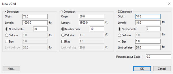
Right-clicking anywhere in the Project Explorer or on the UGrid | Right-clicking anywhere in the Project Explorer or on the UGrid data item will display a menu with '''New UGrid 2D''' and '''New UGrid 3D''' commands. These commands bring up the ''New UGrid'' dialog which specifies options for the creation of a new UGrid, and is very similar to the [[GMS:Creating_and_Editing_3D_Grids#Create_Grid|''Create Grid'']] dialog for 3D structured grids. | ||
[[File:NewUGrid.png|thumb|none|600 px|The ''New UGrid'' dialog]] | |||
==Map → UGrid== | ==Map → UGrid== | ||
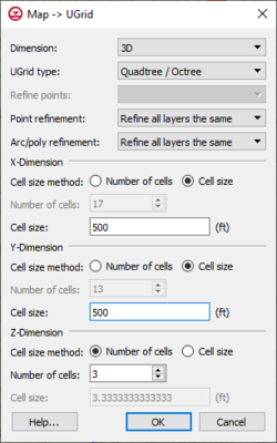
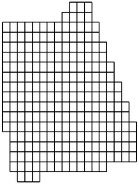
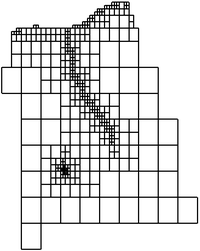
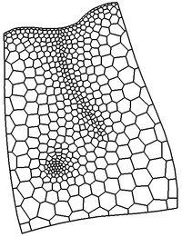
The '''Map → UGrid''' command creates a UGrid from feature objects. It can be found in the ''Feature Objects'' menu, in the Map toolbar, and in some pop-up menus when right-clicking on items in the [[GMS:Project Explorer|Project Explorer]] (Coverage, Grid Frame). The command opens the '' | The '''Map → UGrid''' command creates a UGrid from feature objects. It can be found in the ''Feature Objects'' menu, in the Map toolbar, and in some pop-up menus when right-clicking on items in the [[GMS:Project Explorer|Project Explorer]] (Coverage, Grid Frame). The command opens the ''Map → UGrid'' dialog. | ||
[[Image:DialogCreateUGrid.png|thumb|right|250 px|Map → UGrid dialog.]] | [[Image:DialogCreateUGrid.png|thumb|right|250 px|Map → UGrid dialog.]] | ||
| Line 16: | Line 18: | ||
*''Dimension'' – Specifies whether a 2D or 3D UGrid will be created. | *''Dimension'' – Specifies whether a 2D or 3D UGrid will be created. | ||
*''UGrid type'' | *''UGrid type'' | ||
**''Regular (not refined)'' – Creates a grid with rectangular cells that are not refined. Any refinement attributes specified on feature objects | **''Regular (not refined)'' – Creates a grid with rectangular cells that are not refined. Any refinement attributes specified on feature objects are ignored. | ||
**'' | **''Quadtree'' – Creates a grid with rectangular cells that are refined in a quad tree manner around any points, arcs and polygons which specify the refinement attribute and refinement size. The cells surrounding the points, arcs, and polygons are also refined to smooth change from coarse cells to refined cells. | ||
**''Nested'' – Creates a grid with rectangular cells that are | **''Nested'' – Creates a grid with rectangular cells that are refined like the quadtree option, but the surrounding cells are not smoothed. | ||
**''Voronoi'' – Creates a Voronoi grid with cells of various sizes and shapes which meet the Voronoi criteria. Only the active coverage is used and it must contain a polygon because the algorithm uses the polygon to create a triangular mesh. The mesh is refined around points that are marked as refine points based on the specified refinement size. The mesh is constructed to honor all arc geometry. If refinement is specified as an attribute on arcs or polygons it is ignored. | **''Voronoi'' – Creates a Voronoi grid with cells of various sizes and shapes which meet the Voronoi criteria. Only the active coverage is used and it must contain a polygon because the algorithm uses the polygon to create a triangular mesh. The mesh is refined around points that are marked as refine points based on the specified refinement size. The mesh is constructed to honor all arc geometry. If refinement is specified as an attribute on arcs or polygons it is ignored. | ||
*''Refine points'' – If the ''Quadtree / Octree'' option is selected and refine points exist in multiple coverages, specifies which refine points to use. | *''Refine points'' – If the ''Quadtree / Octree'' option is selected and refine points exist in multiple coverages (available when "Refinement" is selected in the [[GMS:Coverages#Coverage_Setup|Coverage Setup]] dialog), specifies which refine points to use. | ||
*''Point refinement'' – If the ''UGrid type'' is | *''Point refinement'' – If the ''UGrid type'' is "Quadtree / Octree", this combo box shows the option "Refine all layers the same" which will result in all layers having the same number of cells, and the '''Octree''' option which refines and smooths in the vertical direction. | ||
*''Arc/poly refinement'' – Similar to the ''Point refinement'' option for arcs and polygons and with the addition of the option | *''Arc/poly refinement'' – Similar to the ''Point refinement'' option for arcs and polygons and with the addition of the option "Quadtree on assigned layers" which refines horizontally in a quadtree fashion for only the layers that the arcs and polygons are assigned to in the attribute tables. | ||
*''X, Y, Z number of cells'' | *''X, Y, Z number of cells'' | ||
** If not using the Voronoi UGrid type, the size and number of cells in the X, Y and Z dimensions can be specified. For quad tree UGrids, the cell size represents the large, unrefined size. The small, refined size is determined by the refinement specified at points, arcs and polygons. Also for quad tree UGrids, if the cell size is specified, it represents a target cell size (large, unrefined size); the actual cell size will likely be somewhat different so that the cells fit within the grid boundaries. | ** If not using the Voronoi UGrid type, the size and number of cells in the X, Y and Z dimensions can be specified. For quad tree UGrids, the cell size represents the large, unrefined size. The small, refined size is determined by the refinement specified at points, arcs and polygons. Also for quad tree UGrids, if the cell size is specified, it represents a target cell size (large, unrefined size); the actual cell size will likely be somewhat different so that the cells fit within the grid boundaries. | ||
| Line 31: | Line 33: | ||
|+ Various UGrids created from the same coverage. | |+ Various UGrids created from the same coverage. | ||
|- | |- | ||
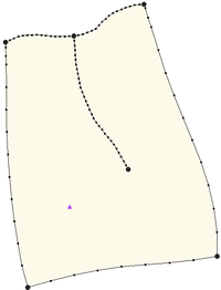
| [[Image:MapToUGridMap.png|thumb|none|Coverage]] | | [[Image:MapToUGridMap.png|thumb|none|200 px|Coverage]] | ||
| [[Image:MapToUGridRegular.png|thumb|none|Regular UGrid]] | | [[Image:MapToUGridRegular.png|thumb|none|200 px|Regular UGrid]] | ||
| [[Image:MapToUGridQuad.png|thumb|none| | | [[Image:MapToUGridQuad.png|thumb|none|200 px|Quadtree UGrid]] | ||
| [[Image:MapToUGridVoronoi.png|thumb|none|Voronoi UGrid]] | | [[Image:MapToUGridVoronoi.png|thumb|none|200 px|Voronoi UGrid]] | ||
|} | |} | ||
==Conversion | ==Conversion from Other Data Types== | ||
The following data types can be converted to UGrids by right-clicking on the object in the [[GMS:Project Explorer|Project Explorer]] and selecting the '''''Convert To | The following data types can be converted to UGrids by right-clicking on the object in the [[GMS:Project Explorer|Project Explorer]] and selecting the '''''Convert To → UGrid''''' command from the pop-up menu. | ||
*[[GMS:TIN Module|TINs]] | *[[GMS:TIN Module|TINs]] | ||
| Line 45: | Line 47: | ||
*[[GMS:2D Mesh Module|2D Mesh]] | *[[GMS:2D Mesh Module|2D Mesh]] | ||
*[[GMS:3D Mesh Module|3D Mesh]] | *[[GMS:3D Mesh Module|3D Mesh]] | ||
*[[GMS:Feature_Objects#Polygons|Polygons]] in a [[GMS:Feature_Objects#Coverages|coverage]] (''Map To | *[[GMS:Feature_Objects#Polygons|Polygons]] in a [[GMS:Feature_Objects#Coverages|coverage]] (''Map To → Polygons → UGrid'') | ||
*Polygon shape files in the [[GMS:GIS Module|GIS Module]] | *Polygon shape files in the [[GMS:GIS Module|GIS Module]] | ||
| Line 57: | Line 59: | ||
If the UGrid has 3D cells, this command brings up a dialog asking for the layer number from which a UGrid consisting of 2D cells will be created. | If the UGrid has 3D cells, this command brings up a dialog asking for the layer number from which a UGrid consisting of 2D cells will be created. | ||
==UGrid Structure== | ==Constraints== | ||
A UGrid is a general purpose unstructured grid that can have a variety of cell types. GMS applies some structure to unstructured grids in the form of "constraints" (previously called "UGrid Structure"). The UGrid's constraint determines the types of cells and the editing operations that are allowed and how they are performed on the UGrid. The constraint of a UGrid is shown in the ''UGrid Properties'' dialog. | |||
*"Quadtree 2D" – Used for 2D grids that were either converted from a 2D or 3D grid or were created using as a Regular, Quadtree, or Nested UGrid. Cells can be refined but not deleted or created and cell boundaries cannot be moved. Points cannot be added, deleted, or moved. | |||
*"Quadtree 3D" – Used for 3D grids that were either converted from a 2D or 3D grid or were created using as a Regular, Quadtree, or Nested UGrid. Cells can be refined but not deleted or created and cell boundaries cannot be moved. Points cannot be added, deleted, or moved. | |||
<!--*''Voronoi'' – Used for grids created using Voronoi option in the ''Map → UGrid'' dialog. For the outer cells of a Voronoi UGrid the computational centroid of the cell is along the outer edge to maintain the right angle connection between cells when generating the MODFLOW UDIS package file. Cells cannot be refined or deleted or created and cell boundaries cannot be moved. Points cannot be added, deleted, or moved.--> | |||
*"Rectilinear 2D" – For a 2D grid. The row and column spacing in the grid can vary, but the row and column boundaries are straight. Each cell center or grid node can have a unique elevation. The grid can also be rotated about the Z axis if desired. Also, cells cannot be created or deleted or refined and, cell boundaries cannot be moved. Points cannot be added, deleted, or moved. | |||
*"Rectilinear 3D" – For a 3D grid. The row and column spacing in the grid can vary, but the row and column boundaries are straight. Each cell center or grid node can have a unique elevation. The grid can also be rotated about the Z axis if desired. Also, cells cannot be created or deleted or refined and, cell boundaries cannot be moved. Points cannot be added, deleted, or moved. | |||
*"2D" – Used for 2D surfaces such as a TIN, mesh, or simply as points without cells. This is the default when creating a new UGrid by clicking points in plan view, and when importing points from a text file and specifying "UGrid Points 2D". Points can be triangulated to form cells and cells can be deleted. Points can be added, deleted, and moved. | |||
*"3D" – Used for 3D surfaces such as a TIN, mesh, or simply as points without cells. This is the default when creating a new UGrid by clicking points in plan view, and when importing points from a text file and specifying "UGrid Points 3D". Points can be triangulated to form cells and cells can be deleted. Points can be added, deleted, and moved. | |||
*"None" – No constraint. Used for all other UGrids. Points can be triangulated to form cells and cells can be deleted. Points can be added, deleted, and moved. | |||
MODFLOW 6 will determine the discretization package based on the UGrid constraints. | |||
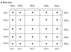
* The DIS package requires a rectilinear 3D UGrid. | |||
* The DISV package can work with any UGrid that is stacked. | |||
* The DISU package requires a non-stacked UGrid. The DISU package is not recommended for use. | |||
{|- | |||
|- | |||
|[[File:Rectilinear-grid.png|thumb|none|250 px|UGrid with rectilinear constraint]] | |||
|[[File:Disv-grid.png|thumb|none|350 px|UGrid examples]] | |||
|} | |||
==Cell Refinement== | |||
UGrid cells can be refined by selecting the cells, right-clicking on them, and selecting the '''Refine''' menu item. A new copy of the UGrid will generated with the selected cells refined. The cells will be refined based on the structure of the UGrid. For a UGrid with quad tree structure a cell is refined by adding an additional level of quadtree refinement. Voronoi structured UGrid cells can only be refined by permanently changing the grid structure to Unknown. For a UGrid with unknown structure, a 3D cell is refined by adding a node at the middle of each horizontal edge along with a new node at the center of the top and bottom faces. | |||
==Deleting Points and Cells== | |||
Selected UGrid points and cells can be deleted by hitting the ''Delete'' key if the current UGrid [[#Constraints (previously "UGrid Structure")|constraint]] allows it. | |||
==Lock to Prevent Editing / Unlock for Editing== | |||
In order to prevent accidental editing of a UGrid, such as dragging a selected point, UGrids can be "locked" and "unlocked". They typically start out locked when they are created, and when locked, no editing is allowed. To unlock the UGrid, simply right-click on the [[File:UGrid 2D Locked.svg|16 px]] [[File:UGrid 3D Locked.svg|16 px]] UGrid in the Project Explorer and select the '''Unlock for Editing''' command. This command changes to say '''Lock to Prevent Editing''' when the UGrid is unlocked, allowing the user to lock the UGrid and thus prevent further editing. | |||
==Triangulate== | |||
UGrid points can be triangulated to form a Delauney triangulated irregular network, or TIN, by right-clicking on the UGrid and selecting the '''Triangulate''' command. If any cells exist they will be deleted and new triangle cells will be created. | |||
==Split Layer== | |||
A UGrid can be divided into multiple layers using the '''Split Layer''' command. Use the '''Select Cells''' tool to right-click on a cell in the UGrid and select the '''Split Layer''' command. Currently, GMS will duplicate the existing UGrid and create the new layer(s) on the duplicate UGrid. To split UGrid layers, the UGrid must be a stacked UGrid where all layers are identical. Layers cannot be split on UGrids containing pinch-outs. | |||
==UGrid Structure, Prior to GMS 10.2== | |||
A UGrid can keep track of the geometric structure it was generated from. The structure can control the editing operations that are allowed and how they are performed on the UGrid. The structure of a UGrid is shown in the UGrid Properties dialog. | A UGrid can keep track of the geometric structure it was generated from. The structure can control the editing operations that are allowed and how they are performed on the UGrid. The structure of a UGrid is shown in the UGrid Properties dialog. | ||
*''Quadtree'' structure is used for grids that were either converted from a 2D or 3D grid or were created using as a Regular, Quadtree, or Nested UGrid. | *''Quadtree'' structure is used for grids that were either converted from a 2D or 3D grid or were created using as a Regular, Quadtree, or Nested UGrid. | ||
*''Voronoi'' structure is used for grids created using Voronoi option in the Map → UGrid | *''Voronoi'' structure is used for grids created using Voronoi option in the ''Map → UGrid'' dialog. For the outer cells of a Voronoi UGrid the computational centroid of the cell is along the outer edge to maintain the right angle connection between cells when generating the MODFLOW UDIS package file. | ||
*''Unknown'' structure is used for all other UGrids. | *''Unknown'' structure is used for all other UGrids. | ||
{{Navbox GMS}} | {{Navbox GMS}} | ||
