SMS:ADCIRC Boundary Conditions: Difference between revisions
| Line 17: | Line 17: | ||
* ''Island'' – This type of boundary represents an island boundary with no normal flow condition and free tangential slip. This can be selected for a closed feature arc. | * ''Island'' – This type of boundary represents an island boundary with no normal flow condition and free tangential slip. This can be selected for a closed feature arc. | ||
* ''Normal Flow'' – This type of boundary represents a river inflow or open ocean boundary with a specified normal flow condition and free tangential slip. Discharges are specified either for harmonic discharge forcing or for time series discharge forcing. | * ''Normal Flow'' – This type of boundary represents a river inflow or open ocean boundary with a specified normal flow condition and free tangential slip. Discharges are specified either for harmonic discharge forcing or for time series discharge forcing. | ||
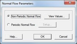
<blockquote> [[Image:ADCIRC Normal BC.jpg|thumb|none|left|250 px|''Normal Flow Parameters'' dialog]] </blockquote> | <blockquote style="margin-top:0px; margin-bottom:0px;"> [[Image:ADCIRC Normal BC.jpg|thumb|none|left|250 px|''Normal Flow Parameters'' dialog]] </blockquote> | ||
* ''Normal Wave Radiation'' – This type of boundary represents an open boundary where waves are allowed to propagate freely out of the domain. | * ''Normal Wave Radiation'' – This type of boundary represents an open boundary where waves are allowed to propagate freely out of the domain. | ||
* ''Mainland Barrier'' – This type of boundary represents a mainland boundary comprised of a dike or levee. Non-zero normal flow is computed using a supercritical, free surface weir formula if the barrier is overtopped. Zero normal flow is assumed if the barrier is not overtopped. | * ''Mainland Barrier'' – This type of boundary represents a mainland boundary comprised of a dike or levee. Non-zero normal flow is computed using a supercritical, free surface weir formula if the barrier is overtopped. Zero normal flow is assumed if the barrier is not overtopped. | ||
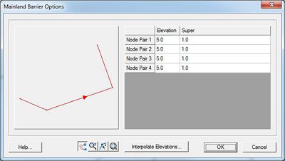
<blockquote style="margin-top:0px; margin-bottom:0px;"> [[Image:ADCIRC Mainland BC.jpg|thumb|none|left|400 px|''Mainland Barrier Options'' dialog]] </blockquote> | |||
* ''Island Barrier'' – This type of boundary represents a dike or levee that lies inside the computational domain. Non-zero normal flow is compute using either subcritical or supercritical, free surface weir formula (based on the water level on both sides of the barrier) if the barrier is overtopped. Zero normal flow is assumed if the barrier is not overtopped. This boundary condition requires two nodestrings with an equal number of nodes. See [[SMS:ADCIRC Weirs and Island Barriers|ADCIRC Weirs and Island Barriers]] for more information. | * ''Island Barrier'' – This type of boundary represents a dike or levee that lies inside the computational domain. Non-zero normal flow is compute using either subcritical or supercritical, free surface weir formula (based on the water level on both sides of the barrier) if the barrier is overtopped. Zero normal flow is assumed if the barrier is not overtopped. This boundary condition requires two nodestrings with an equal number of nodes. See [[SMS:ADCIRC Weirs and Island Barriers|ADCIRC Weirs and Island Barriers]] for more information. | ||
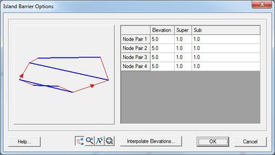
<blockquote> [[Image:ADCIRC Island BC.jpg|thumb|none|left|400 px|''Island Barrier Options'' dialog]] </blockquote> | <blockquote style="margin-top:0px; margin-bottom:0px;"> [[Image:ADCIRC Island BC.jpg|thumb|none|left|400 px|''Island Barrier Options'' dialog]] </blockquote> | ||
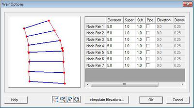
* ''Weir'' – This type of boundary is similar to an Island Barrier with the addition of cross barrier flow. Cross barrier flow simulates flow through the barrier simulating pipes or culverts from one side to the other. Flow rate and direction are based on barrier height, surface water elevation on both sides of the barrier, barrier coefficient and the appropriate barrier flow formula. In addition cross barrier pipe flow rate and direction are based on pipe crown height, surface water elevation on both sides of the barrier, pipe friction coefficient, pipe diameter and the appropriate pipe flow formula. This boundary condition requires two nodestrings with the same number of nodes. See [[SMS:ADCIRC Weirs and Island Barriers|ADCIRC Weirs and Island Barriers]] for more information. | * ''Weir'' – This type of boundary is similar to an Island Barrier with the addition of cross barrier flow. Cross barrier flow simulates flow through the barrier simulating pipes or culverts from one side to the other. Flow rate and direction are based on barrier height, surface water elevation on both sides of the barrier, barrier coefficient and the appropriate barrier flow formula. In addition cross barrier pipe flow rate and direction are based on pipe crown height, surface water elevation on both sides of the barrier, pipe friction coefficient, pipe diameter and the appropriate pipe flow formula. This boundary condition requires two nodestrings with the same number of nodes. See [[SMS:ADCIRC Weirs and Island Barriers|ADCIRC Weirs and Island Barriers]] for more information. | ||
<blockquote> [[Image:ADCIRCWeir5.jpg|thumb|none|left|400 px| ''Weir Options'' dialog.]] </blockquote> | <blockquote style="margin-top:0px; margin-bottom:0px;"> [[Image:ADCIRCWeir5.jpg|thumb|none|left|400 px| ''Weir Options'' dialog.]] </blockquote> | ||
* ''Zero Normal Velocity Gradient'' – This type of boundary forces flow through the specified nodestring reflective of flow at a fictitious point inside the domain. This is referred to as a weakly reflective boundary in some numerical engines. The fictitious point lies on the inward directed normal to the boundary a distance equal to the distance from the boundary node to its farthest 'neighbor. This should ensure that the fictitious point does not fall into an element that contains the boundary node. The velocity at the fictitious point is determined by interpolation. | * ''Zero Normal Velocity Gradient'' – This type of boundary forces flow through the specified nodestring reflective of flow at a fictitious point inside the domain. This is referred to as a weakly reflective boundary in some numerical engines. The fictitious point lies on the inward directed normal to the boundary a distance equal to the distance from the boundary node to its farthest 'neighbor. This should ensure that the fictitious point does not fall into an element that contains the boundary node. The velocity at the fictitious point is determined by interpolation. | ||
* ''Ocean'' – This type of boundary represents an open interface for flow with a specified water surface elevation. Elevations are specified either as tidal constituents for harmonic forcing or as time series or water level. | * ''Ocean'' – This type of boundary represents an open interface for flow with a specified water surface elevation. Elevations are specified either as tidal constituents for harmonic forcing or as time series or water level. | ||
Revision as of 20:39, 7 April 2016
Much of ADCIRC's versatility as a model is due to the large number of different boundary types and boundary conditions available in the model. For detailed description of the ADCIRC boundary conditions, see the documentation provided by the ADCIRC development group at http://www.adcirc.org.
ADCIRC Boundary Conditions Nodestrings
Boundary conditions are assigned by setting attributes to Feature Arcs representing boundary arcs in the domain used in the sifmulation.
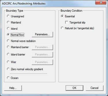
The ADCIRC Arc/Nodestring Attributes dialog defines the type of boundary conditions for each feature arc/nodestring.
A feature arc/nodestring can be defined as mainland, island, normal flow, mainland barrier, island barrier, tidal constituents, etc.
To set the boundary types, choose the Select Feature Arc tool from the Toolbox and double-click the desired arc to open the ADCIRC Arc/Nodestring Attributes dialog; then assign the desired boundary conditions to the arc.
ADCIRC Boundary Types
Boundary types are assigned to feature arcs in the conceptual mode or nodestrings on the ADCIRC mesh. Correct boundary type assignments are very important to run a successful ADCIRC project. The following boundary types are available in SMS for ADCIRC:
- Unassigned – Default, no boundary condition assigned
- Mainland – This type of boundary represents a mainland boundary with no normal flow condition and free tangential slip.
- Island – This type of boundary represents an island boundary with no normal flow condition and free tangential slip. This can be selected for a closed feature arc.
- Normal Flow – This type of boundary represents a river inflow or open ocean boundary with a specified normal flow condition and free tangential slip. Discharges are specified either for harmonic discharge forcing or for time series discharge forcing.
- Normal Wave Radiation – This type of boundary represents an open boundary where waves are allowed to propagate freely out of the domain.
- Mainland Barrier – This type of boundary represents a mainland boundary comprised of a dike or levee. Non-zero normal flow is computed using a supercritical, free surface weir formula if the barrier is overtopped. Zero normal flow is assumed if the barrier is not overtopped.
- Island Barrier – This type of boundary represents a dike or levee that lies inside the computational domain. Non-zero normal flow is compute using either subcritical or supercritical, free surface weir formula (based on the water level on both sides of the barrier) if the barrier is overtopped. Zero normal flow is assumed if the barrier is not overtopped. This boundary condition requires two nodestrings with an equal number of nodes. See ADCIRC Weirs and Island Barriers for more information.
- Weir – This type of boundary is similar to an Island Barrier with the addition of cross barrier flow. Cross barrier flow simulates flow through the barrier simulating pipes or culverts from one side to the other. Flow rate and direction are based on barrier height, surface water elevation on both sides of the barrier, barrier coefficient and the appropriate barrier flow formula. In addition cross barrier pipe flow rate and direction are based on pipe crown height, surface water elevation on both sides of the barrier, pipe friction coefficient, pipe diameter and the appropriate pipe flow formula. This boundary condition requires two nodestrings with the same number of nodes. See ADCIRC Weirs and Island Barriers for more information.
- Zero Normal Velocity Gradient – This type of boundary forces flow through the specified nodestring reflective of flow at a fictitious point inside the domain. This is referred to as a weakly reflective boundary in some numerical engines. The fictitious point lies on the inward directed normal to the boundary a distance equal to the distance from the boundary node to its farthest 'neighbor. This should ensure that the fictitious point does not fall into an element that contains the boundary node. The velocity at the fictitious point is determined by interpolation.
- Ocean – This type of boundary represents an open interface for flow with a specified water surface elevation. Elevations are specified either as tidal constituents for harmonic forcing or as time series or water level.
ADCIRC Boundary Conditions Options
Depending upon the specified boundary type, the following boundary conditions are available:
| Boundary Condition | Boundary Type |
|---|---|
| Essential w/ Tangential Slip |
Mainland Island Normal Flow Mainland Barrier |
| Essential w/o Tangential Slip |
Mainland Island Normal Flow Mainland Barrier |
| Natural (w/ Tangential Slip) |
Mainland Island Normal Flow Mainland Barrier |
| Tidal Constituents | Ocean |
| Curve | Ocean |
| Extract from Dataset | Ocean |
Recording Stations
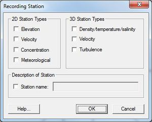
The SMS interface allows creating recording stations at specified nodal locations. At these locations, the ADCIRC model will output specified quantities at a user specified time interface. This allows for comparison of time series with observed buoy data. For example, the global output interval may be 30 minutes or 1 hour, while the recording station output could be at a higher frequency such as 6 minutes.
The following recording stations can be assigned to an ADCIRC mesh node:
2D Station Types
2D station options include:
- Elevation – ADCIRC will output a times series of computed water surface elevation at this location.
- Velocity – ADCIRC will output a times series of computed velocity magnitude at this location.
- Concentration – ADCIRC will output a times series of constituent concentration at this location.
- Meteorological – ADCIRC will output a times series of wind and pressure variables at this location.
3D Station Types
These options are only available when running in 3D mode.
- Density/Temperature/Salinity
- Velocity
- Turbulence
Description of Station
Stations can be assigned a name to make station identification easier. A single point can be a recording station for multiple types of data (i.e. a node can record both elevation and velocity).
Related Links
- ADCIRC
- Coverage
- Linear Truncation Error Analysis (LTEA)
- Meshes
- Model Control
- Spatial Attributes
- Steering
SMS – Surface-water Modeling System | ||
|---|---|---|
| Modules: | 1D Grid • Cartesian Grid • Curvilinear Grid • GIS • Map • Mesh • Particle • Quadtree • Raster • Scatter • UGrid |  |
| General Models: | 3D Structure • FVCOM • Generic • PTM | |
| Coastal Models: | ADCIRC • BOUSS-2D • CGWAVE • CMS-Flow • CMS-Wave • GenCade • STWAVE • WAM | |
| Riverine/Estuarine Models: | AdH • HEC-RAS • HYDRO AS-2D • RMA2 • RMA4 • SRH-2D • TUFLOW • TUFLOW FV | |
| Aquaveo • SMS Tutorials • SMS Workflows | ||
