GMS:Solid Module: Difference between revisions

From XMS Wiki
Jump to navigationJump to search
No edit summary
No edit summary
Line 4: Line 4:
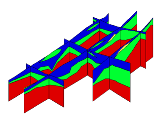
Once such a model is created, [[GMS:Cross_Sections#Solid_Cross_Sections|cross sections]] can be cut anywhere on the model to create fence diagrams.


<gallery widths="350 px" heights="275 px">
<gallery widths="325 px" heights="250 px">
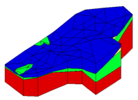
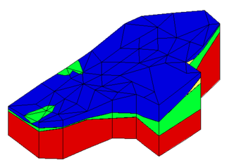
Image:solids.png|Example of a solid created in GMS
Image:xsect.png|Example of fence diagrams created using solids

Revision as of 15:11, 24 October 2017

Solid Module
Solids.png
Solid
Solid Properties
Solid Primitives
Solid Cross Sections
More
Boundary Matching
HUF Package
Horizons to Solids
Solid Display Options
Solid Module Tool Palette
Solids to HUF
Solids to Layered Mesh
Solids to MODFLOW Command
Solid Commands

The Solid module of GMS is used to construct three-dimensional models of stratigraphy using solids. The module contains its own set tools and menu commands that can be used to modify solid data. Properties for solid data can be viewed and edited. The module also has its own display options for convenience in visualizing solid data.

Once such a model is created, cross sections can be cut anywhere on the model to create fence diagrams.

Solids are used for site characterization and visualization. Solids can also be used to define layer elevation data for MODFLOW models using the Solids → MODFLOW command or Solids to HUF and to define a layered 3D mesh using the Solids → Layered Mesh.