GMS:Boundary Matching

One of the three basic options associated with the Solids → MODFLOW command is the Boundary Matching option. The goal of the boundary matching algorithm is to compute a set of elevation arrays that honor the boundaries between the stratigraphic units as closely as possible.
Contents
Solids and Layer Ranges
Next a layer range must be assigned to each solid. The layer range represents the consecutive sequence of layer numbers in the MODFLOW grid that are to coincide with the solid model. A sample set of layer range assignments is shown in the figure below (a). The example in the figure below is a case where each solid is continuous through the model domain and there are no pinchouts. Each of the solids is given a layer range defined by a beginning and ending grid layer number. The resulting MODFLOW grid is shown in the figure below (b).

A more complex case with pinchouts is illustrated in the next figure (a). Solid A is given the layer range 1–4, and the enclosed pinchout (solid B) is given the layer range 2–2. The set of grid layers within the defined range that are actually overlapped by the model may change from location to location. The layer range represents the set of grid layers potentially overlapped by the solid anywhere in the model domain. For example, on the left side of the problem shown in the figure below (a), solid A covers grid layers 1, 2, 3 and 4. On the right side of the model, solid A is associated with grid layers 1, 3 and 4 since the enclosed solid (solid B) is associated with layer 2. Likewise, Solid C is associated with grid layers 5 and 6 on the left side of the model but only with layer 6 on the right side of the model where solid D is associated with layer 5. The resulting MODFLOW grid is shown in the figure below (b).

When assigning layer ranges to solids, care must be taken to define associations that are topologically sound. For example, since solid B in the figure above (a) is enclosed by solid A, solid B could not be assigned a layer range that is outside the layer range of solid A.
Layer ranges are assigned using the Solids Properties dialog.
Solids → MODFLOW Command
The final step is to select the Solids → MODFLOW command in the Solids menu. The layer elevations and material properties for the 3D grid will then be automatically assigned from the solids as shown below.

The following images represent cross sections at selected locations of the grid shown above. Notice that the grid elevations precisely match the stratigraphic boundaries defined by the solids while maintaining the continuous layers required by MODFLOW.
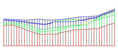
Sample cross section
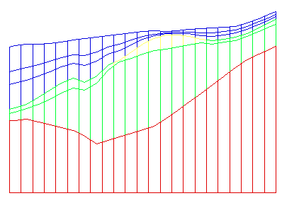
Sample cross section


Smoothing Tolerance
When the Solids → MODFLOW command is executed with the Boundary Matching option, it is common to have seams that occupy only a portion of a layer as shown in the above cross sections. The top and bottom elevations for cells adjacent to these seams must be adjusted by GMS using a "smoothing" process to ensure that there are not drastic cell size differences in the horizontal direction from one cell to the next. The smoothing is accomplished by iteratively changing the elevation of selected cells until the cell elevations change less than the Smoothing Tolerance specified in the Solids → MODFLOW Options dialog.
Minimum Thickness
This option enables avoiding extremely thin layers at edges of pinchouts and represents the minimum thickness of grid cells created from the solids. Solids with thickness less than this amount are ignored and the surrounding material is used instead. This property is assigned in the solids Properties dialog. The figure below demonstrates the application of this property.
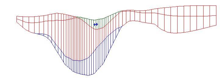
Small minimum thickness
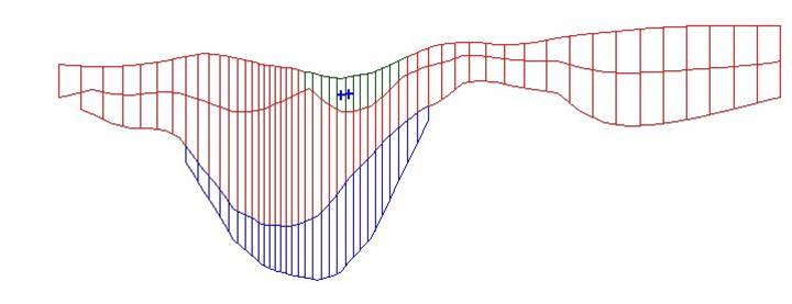
Larger minimum thickness


Top Cell Bias
The top cell bias is the percentage of the thickness which is assigned to the top layer of the MODFLOW grid create from the solids. The thickness of the top layer increases as the top cell bias increases. A large top cell bias can be used to prevent top-layer cells from going dry. This property is assigned in the solids Properties dialog.
Related Links
| [hide]GMS – Groundwater Modeling System | ||
|---|---|---|
| Modules: | 2D Grid • 2D Mesh • 2D Scatter Point • 3D Grid • 3D Mesh • 3D Scatter Point • Boreholes • GIS • Map • Solid • TINs • UGrids | |
| Models: | FEFLOW • FEMWATER • HydroGeoSphere • MODAEM • MODFLOW • MODPATH • mod-PATH3DU • MT3DMS • MT3D-USGS • PEST • PHT3D • RT3D • SEAM3D • SEAWAT • SEEP2D • T-PROGS • ZONEBUDGET | |
| Aquaveo | ||