GMS:Horizons to Solids

The following steps illustrate how to use the Horizons method to create solid stratigraphy.
- Create/Import Inputs – There are three main types of inputs for the horizons method:
- Boreholes – Boreholes can be created by importing borehole data by using the File Import Wizard, importing sample data after boreholes already exist, or using the borehole tools to manually enter the boreholes. Once a borehole has been created it can be edited in the Borehole Editor or by using the borehole tools. Also an existing borehole can be copied. Boreholes can be locked to prevent them from being edited.
- TINs – TINs can be created 3 different ways in GMS: manually entering the vertex locations and triangulating, converting a different GMS data type to a TIN, and copying a currently existing TIN. (See Creating TINs)
- Raster Catalog – a set of rasters defining the top of each horizon (available beginning in version 9.0).
- Assign Horizon IDs – The term “horizon” refers to the top of each stratigraphic unit that will be represented in a corresponding solid, HUF unit or material layer. Horizons are numbered consecutively in the order that the strata are “deposited” (from the bottom up). (See Horizons)
- Create Primary TIN – A TIN must be created or imported into GMS to be used as the primary TIN for the horizons method. The primary TIN defines the boundary of the solids that will be generated. Also, the density of the triangles in the primary TIN controls the density of the triangles in the solids that are created. (See Creating TINs)
- Setup additional optional inputs – Two additional options exist to help constrain and provide user intervention in the horizon modeling process. The two options are to create borehole cross sections or a horizon conceptual model.
- Run the Horizons Wizard – Select the Horizons→Solids command in the Borehole or TINs menu.
Horizon → Solid Algorithm
When the Horizon→Solids command is executed the horizons specified on the borehole contacts or TIN nodes are converted to a set of scatter points with one dataset for each horizon. The scatter points are then used to interpolate a surface for each horizon. Starting with the lowest numbered horizon, the surface is extruded down to create a solid. The surface corresponding to the next horizon is then extruded down to fill in the space between that surface and the previous surface. This process is repeated for each surface. At each step, a solid is created for the current horizon and all previously defined solids are subtracted from that solid, resulting in an incremental buildup of the stratigraphy from the bottom to the top. The entire process is simpler, more intuitive, and more robust than the old set operations approach.
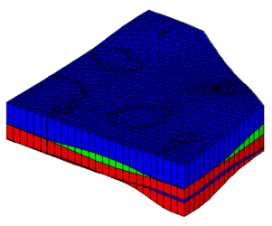
Solids created from the horizons method
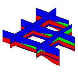
Cross sections from the solid created via the horizons method


| [hide]GMS – Groundwater Modeling System | ||
|---|---|---|
| Modules: | 2D Grid • 2D Mesh • 2D Scatter Point • 3D Grid • 3D Mesh • 3D Scatter Point • Boreholes • GIS • Map • Solid • TINs • UGrids | |
| Models: | FEFLOW • FEMWATER • HydroGeoSphere • MODAEM • MODFLOW • MODPATH • mod-PATH3DU • MT3DMS • MT3D-USGS • PEST • PHT3D • RT3D • SEAM3D • SEAWAT • SEEP2D • T-PROGS • ZONEBUDGET | |
| Aquaveo | ||